


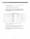


Generally speaking, there are two rules to follow when connecting equipment outputs
to the inputs of other equipment.
1. Properly match the impedances of the outputs and inputs.
2. Connect low impedance outputs to high impedance inputs.
It goes without saying that not only input and output impedance matching, but also
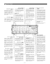
level matching should be taken into consideration. Each input channel of the MX-104
is provided with an Input Level Control that includes a negative feedback (NF)
circuitry, so the usable signal level range is wide. Input impedances and levels are
shown in the following table.
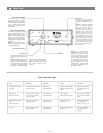
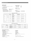
*Sensitivity is the level required to produce a program out level of +4dB.
*0dB is referenced to 0.775V RMS.
All XLR Type connectors are electronic balanced. Phone jack is unbalanced.
If the line going from one piece of equipment to another is long (more than 5m), we
recommend that balanced outputs be connected to balanced inputs.
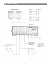
As is described in the beginning of the Operating Instructions Manual, the connectors
of the MX-104 are wired as follows: Pin 1 is ground (shield). Pin 2 is cold (low, minus).
Pin 3 is hot (high, plus).
INPUT SPECIFICATIONS
CONNECTION
INPUT
ACTUAL
LOAD
IMPEDANCE
FOR USE
WITH
NOMINAL
SENSITIVITY*
(PGM OUTPUT
LEVEL +4dB)
CONNECTOR
CH1
CH4
AUX
GEQ
PWR/AMP
LOW Z
HIGH Z
-60dB (0.78mV)
-35dB (13.8m V)
-20dB (77.5mV)
+4dB (1.23V)
+4dB (1.23V)
XLR TYPE NC3F
PHONE JACK
RCA PIN JACK
PHONE JACK
PHONE JACK
PHONE JACK
OPEN
MICRO-
PHONES
LOWER IMP
LINES
LOWER IMP,
LINES
LOWER IMP,
LINES
LOWER IMP,
LINES
— 6 —
Input Connections