


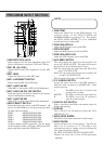
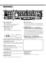


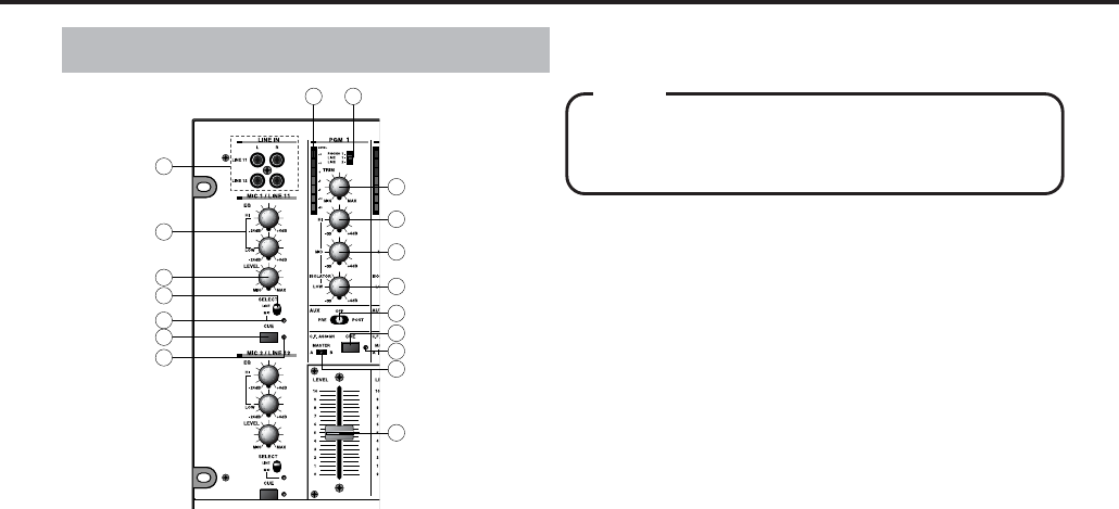
qLINE INPUT RCA JACK
Input connectors for line level equipment such as CD
players, MD players, tape decks, DAT and VTR etc.
wMIC EQ (HI/LOW)
Adjusts the HI and LOW frequencies for the MIC
input.
eMIC LEVEL
Adjusts the input level of the MIC input.
rMIC/LINE SELECT SWITCH
Selects between MIC and LINE input.
tMIC/LINE CUE LED
When MIC is selected this LED will be illuminated.
yMIC/LINE CUE ON/OFF SWITCH
Sends the signal from the mic channel to the monitor
section for headphone monitoring.
uMIC/LINE CUE LED
When CUE is selected this LED will be illuminated.
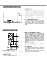
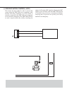
iINPUT SELECT SWITCH
Selects the input to be sent to each PGM channel. On
the five (5) main PGMs you can select from up to three
(3) input sources as follows.
PGM-1 PHONO1/LINE1/LINE2
PGM-2 PHONO2/LINE3/LINE4
PGM-3 PHONO3/LINE5/LINE6
PGM-4 PHONO4/LINE7/LINE8
PGM-5 PHONO5/LINE9/LINE10
All phono inputs are RIAA equalized. The line inputs
can be assigned to either a CD player, MD player, DAT
player, tape deck or other like LINE device.
oPGM TRIM
Adjusts the input level of each PGM channels. For
acoustic clarity, set the INPUT FADER and
MASRER FADER to a position of 7-8. Then adjusts
the INPUT LEVEL METER
!7 so as to established
an indicated level of about 0dB.
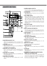
!0PGM ISOLATOR HI
Adjusts the HI frequency level of each PGM.
!1ISOLATOR MID
Adjusts the MID frequency level of each PGM.
!2PGM ISOLATOR LOW
Adjusts the LOW frequency level of each PGM.
!3AUX SEND SWITCH
This switch enables the signal from each program to be
sent to AUX SEND JACK
$9
. This signal can be sent to
the AUX device in the following three (3) ways;
PRE: The signal before the input fader (after EQ) will be
sent to AUX SEND JACK.
POST: The signal after the input fader and crossfader will
be sent to AUX SEND JACK.
OFF: No signal will be sent to AUX SEND JACK.
!4C.F. ASSIGN SWITCH
Assigns the signals from each of the PGM channels to
either side of the crossfader or to MASTER OUT. There
are three positions;
A
The PGM is sent to the "A" position or left
position of the crossfader.
MASTER
The PGM is sent directly to the master out.
B
The PGM is sent to the "B" position or
right side of the crossfader.
!5CUE ON/OFF SWITCH
Sends a signal from each PGM to the monitor section for
headphone monitoring.
!6CUE LED
This LED will be illuminated when the CUE
SWITCH
!5 is on.
!7INPUT LEVEL METER
The LED bar level meters indicate the L and R outputs.
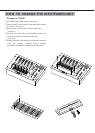
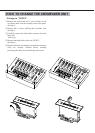
!8INPUT FADER
Adjusts the Input level of each program. Typically this
fader is set to a position of 7-8. This fader is user
replaceable and may be changed easily by following this
users guide's instructions carefully.
See "HOW TO CHANGE THE INPUT FADER UNIT".
*Replace this fader with a Vestax IF-500 replacement
inputfader.
NOTE
PROGRAM INPUT SECTION