


BOTH
L 3 2 1 3 2 1
3
4
INSERT INSERT INSERT INSERT
2 1
R
VIDEO 0UTPUT
GND GND
VIDEO INPUT
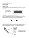
REMOTE
KEY CONTROL
SERIAL NUMBER
10V
CAUTION:
TO REDUCE THE RISK OF FIRE
REPLACE ONLY WITH THE SAME TYPE FUSE
WARNING: TO REDUCE THE RISK OF
FIRE OR ELECTRICAL SHOCK
DO NOT EXPOSE THIS EQUIPMENT
TO RAIN OR MOISTURE
12
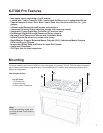
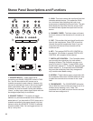
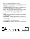
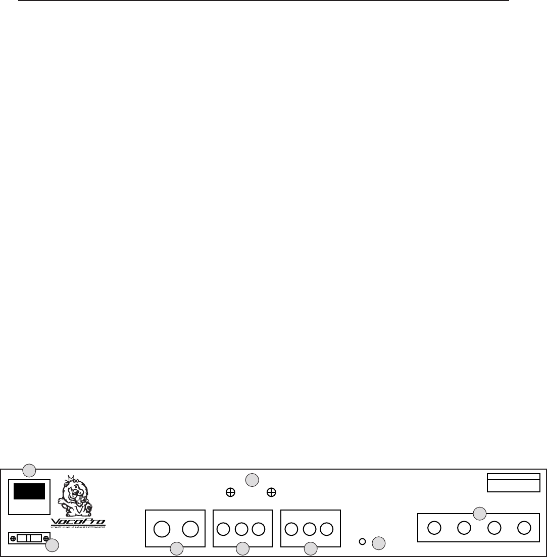
Rear Panel Descriptions and Functions
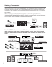
AC INPUT – This is the terminal for the AC power cable. Carefully insert the AC power cable here. The
AC power cable should fit plush and firm into housing.
VOLTAGE SELECTOR - The VOLTAGE SELECTOR is a switch that can change the voltage from 115V
to 230V. Before your KJ-7000 Pro is shipped from the factory, the switch is set to 115V. If you live in an
area that has different voltage requirements (230-240V), you MUST set it to 230V.
BOOTH OUT – These 1/4” jacks are for sending audio to BOOTH/MONITOR speakers. The output level
to the BOOTH/MONITOR speakers is controlled via the BOOTH fader. Connect an appropriate cable from
these jacks to your BOOTH/MONITOR speakers. Note: If your Booth/Monitor speakers do not have a
built-in amplifier, you will need to connect them to a dedicated amplifier to power them.
VIDEO OUT (3) – These jacks send graphics to video display device(s) i.e. TV’s, TFT’s and Monitors.
Connect composite video cables from these VIDEO OUT to the VIDEO IN jacks on your video display
device(s).
VIDEO IN (3) – These jacks allow the video component of A/V devices i.e. CD+G, VCD, LD players to be
connected to the KJ-7000 Pro. Connect composite video cables from these VIDEO IN jacks to the VIDEO
OUT jacks on you A/V device(s).
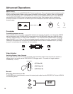
REMOTE KEY CONTROL – This 1/8” jack is for connecting a REMOTE KEY CONTROL cable. Remote
Key Control allows you to make key changes away from the KJ-7000 Pro Digital Key Controller. For
example, a singer with a Remote Key Control enabled microphone can make Key changes by using the
microphones own control set.
INSERT – These jacks are for connecting out-board effects units. The audio from the XLR/ 1/4” channels
are routed out the INSERT jacks to your out-board effects unit(s) and routed back with the effects applied.
Note: In order to use these jacks, you will need appropriate insert cables.
GROUND TERMINALS – These TERMINALS are for connecting ground wires. If you are experiencing
line noise, attach wire from here to your other devices or similar suitable surface.
1.
2.
3.
4.
5.
6.
7.
8.
1
2
3 4 5
6
7
8