


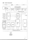

DX7 CIRCUIT DESCRIPTION
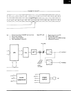
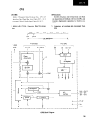
1. Keyboard and Panel Switch Scanning
The 4 bits BO ~ B3 from the sub-CPU (6805S) are input to the decoder (40H138).
The decoder output is sent to the keyboard transfer contacts and the panel switches.
The on or off state of the keyboard break contacts, make contacts and panel switches are sent to
the sub-CPU AO ~ A7 lines via a line driver (40H240) when the sub-CPU B4 and B5 lines are
low.
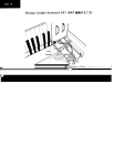
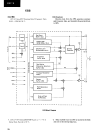
2. Key ON/OFF and Touch Data
The time it takes for the transfer contact to connect with the make contact after separating from
the break contact is recorded by the sub-CPU timer. This value is the Touch data.
The key ON signal is generated when the transfer contact connects with the make contact, and
the key OFF signal is generated when the transfer contact connects with the break contact.
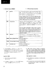
3. ADC
Data entry
Pitch bend wheel
Modulation wheel
Foot controller
Breath controller
After-touch controller
Battery voltage
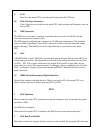
The 7 analog control voltages given above are fed to the ADC (M58990P-l). The analog input
selected by the sub-CPU BO~ B2 bits is converted to a digital value when the sub-CPU B7 line
goes low. The ADC outputs a high level to the sub-CPU C3 line when the conversion is complete.
The ADC sends the 8-bit digital value to the sub-CPU when the sub-CPU B6 line goes low.
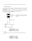
4. Data Transmission from Sub-CPU to Main CPU
4-1. When a key event occurs the sub-CPU CO line goes high, changing the state of the
ready flag (R S F/F) causing the main CPU IRQ and P21 lines to go low.
4-2. The main CPU accepts one byte of data on lines AO~ A7 from the sub-CPU when
the P21 line goes low.
4-3. Once this byte is accepted, pin 9 of IC24 goes low, changing the state of F/F and
forcing the sub-CPU Cl line low.
4-4. When the sub-CPU Cl line goes low, step 4-1 (above) is repeated and then in step
4-2 a second byte of data is accepted by the main CPU.
4-5. During the IRQ routine the main CPU P20 line holds C2 on the sub-CPU line low
until the second byte has been transferred.