


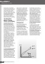

Controls and Connectors
22
EMX512SC/EMX312SC/EMX212S
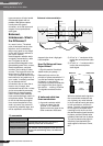
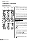
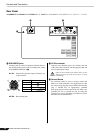
Digital Effects Section
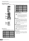
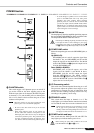
0 PROGRAM dial
Selects the type of effect to be used. You can select from
16 different effect types, as follows.
A PARAMETER knob
Adjusts the parameter (depth, speed, etc.) associated
with the selected effect type.
The mixer saves the last value used with each effect
type. When you change to a different effect type, the
mixer automatically restores the value that was previ-
ously used with that type (regardless of the current
position of the PARAMETER knob). But note that all
values return to their defaults at power-off.
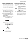
B ON switch
Switches use of the internal effector on or off. The inter-
nal effect is applied only if this switch is on. Note that
the lamp above the switch lights up orange to indicate
that the switch is on. As an alternative to the ON switch,
you can use a separately sold FC5 foot switch to toggle
the effector on and off.
The internal effector is automatically turned on when-
ever you switch on the mixer’s power.
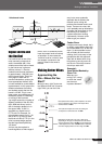
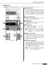
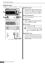
C EFFECT OUT jack
This unbalanced phone output jack outputs the signal
from the EFFECT bus. You can use this jack to output
the signal to an external effector. You can then return the
signal by connecting the external effector to any of the
LINE jacks on channel pairs 5/6 to 11/12.
If you are returning a signal from an external effector
into a LINE jack on any channel pair 5/6 to 11/12,
please be sure to turn the EFFECT knob for that chan-
nel pair to “0”.
D FOOT SW jack
This phone input jack can connect to the (separately
sold) YAMAHA FC5 foot switch. With the foot switch
connected, you can use your foot to toggle the internal
effector ON and OFF.
No. Program Parameter
1
REVERB HALL 1 REVERB TIME
2
REVERB HALL 2 REVERB TIME
3
REVERB ROOM 1 REVERB TIME
4
REVERB ROOM 2 REVERB TIME
55
55
REVERB STAGE 1 REVERB TIME
66
66
REVERB STAGE 2 REVERB TIME
77
77
REVERB PLATE REVERB TIME
88
88
DRUM AMBIENCE REVERB TIME
A
C
B
D
0
9
KARAOKE ECHO DELAY TIME
0
VOCAL ECHO DELAY TIME
A
CHORUS 1 LFO FREQ
B
CHORUS 2 LFO FREQ
CC
CC
FLANGER LFO FREQ
DD
DD
PHASER LFO FREQ
EE
EE
AUTO WAH LFO FREQ
FF
FF
DISTORTION DRIVE
No. Program Parameter
NOTE
NOTE