


Input/Output Panel
9
EMX620—Owner’s Manual
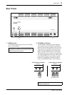
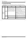
Input/Output Panel
1
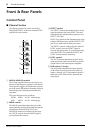
Hi-Z, Lo-Z (inputs 1–4)
These are the input connectors for input chan-
nels 1 through 4. Both the Hi-Z and Lo-Z input
can be used with microphones and, by using the
PAD switch, can also be used with line-level
sources, such as synthesizers and drum machines.
Switchable +15 V phantom power is available to
the Lo-Z XLR-type input for use with con-
denser-type microphones.
Both the Hi-Z and Lo-Z inputs are balanced.
Pin connections are as follows.
B
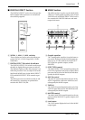
LINE 1 & 2 (input 5)
These two phone jacks are the input connectors
for input channel 5. They are unbalanced, can be
used simultaneously, and are appropriate for use
with line-level sources, such as synthesizers and
drum machines.
C
INST 1 & 2 (input 6)
These two phone jacks are the input connectors
for input channel 6. They are unbalanced, can be
used simultaneously, and their high input imped-
ance makes them ideal for use with instruments
such as electric-acoustic guitar and electric bass.
They can also be used with line-level sources,
such as synthesizers and drum machines.
D
EFFECT OUT jack
The EFFECT OUT phone jack outputs the signal
from the EFFECT bus and can be connected to
the input of an external effects processor.
E
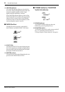
FOOT SW jack
The FOOT SW jack is used to connect an
optional footswitch, such as the Yamaha FC5,
which can be used to turn the built-in digital
effects processor on and off. The DIGITAL
EFFECT ON switch must be in the ON position
in order to use the footswitch.
F
AUX IN—INPUT TO MAIN jack
The AUX IN—INPUT TO MAIN phone jack is
used to feed signals from an external source to
the MAIN bus and can be connected to the out-
put of an external effects processor, for example.
G
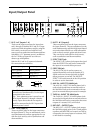
TAPE IN—INPUT TO MAIN jacks
The TAPE IN—INPUT TO MAIN phono jacks
are used to feed signals from an external source to
the MAIN bus and can be connected to the stereo
outputs of a cassette, DAT, or MD deck.
H
REC OUT—OUTPUT jacks
The REC OUT—OUTPUT phono jacks output
the MAIN bus signal prior to the 7-band graphic
equalizer and MASTER level control, and can be
connected to the stereo inputs of a cassette, DAT,
or MD deck for recording.
Hi-Z
Lo-Z
Hi-Z
Lo-Z
Hi-Z
Lo-Z
Hi-Z LINE
Lo-Z
1
LINE
2
INST
1
INST
EFFECT OUT
FOOT SW
2
PHONES
MAIN
MONITOR
INPUT
TO MAIN OUTPUT
11
22
TAPE
IN
AUX IN
REC
OUT
21 3 5 6 78 9 0
A
4
Lo-Z (XLR-type) Hi-Z (TRS phone jack)
Pin 1: ground Sleeve: ground
Pin 2: hot (+) Ring: cold (–)
Pin 3: cold (–) Tip: hot (+)
Note:
The Lo-Z and Hi-Z input of each channel
cannot be used simultaneously. Use the input
appropriate for the source.
Note:
Since phantom power is turned on and
off for inputs channels 1 through 4 simulta-
neously, input devices that do not require it
should be connected to the Hi-Z input when
phantom power is used.
GND
RST
+-
GND
+-