


6
Front and rear panel
EMX660—Owner’s Manual
■
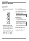
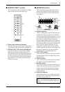
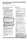
MAIN section
This section allows you to adjust the tone and
volume of the MAIN bus, the mix level of the
built-in effect, and the mix level of the external
input.
C
Graphic equalizer
This is a 7-band graphic equalizer that allows you
to adjust the frequency response of the MAIN
bus signal, providing a maximum of ±12 dB of
cut/boost for each frequency band.
This graphic equalizer affects both the MAIN bus
signal that is output to the speakers and the line
level signal which is output from the MAIN jack
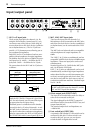
(input/output panel
6
).
D
EFFECT RTN control
This adjusts the level of the effect signal which is
returned from the built-in digital effect to the
MAIN bus.
E
AUX IN control
This adjusts the amount of signal that is sent
from the AUX IN jack to the MAIN bus.
F
TAPE IN
This adjusts the amount of signal that is sent
from the TAPE IN jacks to the MAIN bus.
G
MASTER control
This adjusts the final level of the MAIN bus. It
affects both the MAIN bus signal which is output
from the speakers, and the line level signal which
is output from the MAIN jack (input/output
panel
6
).
H
Peak level indicator
This indicator allows you to monitor the level of
the signal which is output from the MAIN jack
(input/output panel
6
).
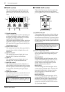
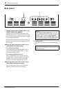
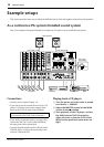
■
POWER AMP section
This section allows you to select the signals that
will be output from the built-in two-channel
power amplifier, and to select the BRIDGE mode.
I
LIMITER indicator
This indicator lights up when the level of the sig-
nal output from the power amp section reaches
the maximum and the limiter is activated. Adjust
appropriate control so that the indicator lights up
for only a short while when the signal reaches the
maximum level.
J
Power amp select switch
Select one of the following three settings to spec-
ify the signals that will be output from power
amp 1/2.
• MAIN BRIDGE
With this setting, the MAIN bus signal will be
output from the BRIDGE jack. The two power
amp channels (A and B) will be bridge con-
nected. Only the MASTER control
G
in the
MAIN section becomes effective.
•
MAIN-MAIN
With this setting, the MAIN bus signal will be
output from the POWER AMP 1 A/B jacks and
from the POWER AMP 2 A/B jacks. Only the
MASTER control
G
in the MAIN section
becomes effective.
• MAIN-MONITOR
With this setting, the MAIN bus signal will be
output from the POWER AMP 1 A/B jacks and
the MONITOR bus signal is output from the
POWER AMP 2 A/B jacks. Only the MASTER
controls in the MAIN and MONITOR sections
G
,
A
are both effective.
Note:
To avoid distortion, adjust the MASTER
control (
G
) so that the 0 indicator lights occa-
sionally.
MAIN
MASTER
TAPE IN
AUX INEFFECT RTN
+6
+3
0
–5
–10
+12
•
6
•
0
•
6
•
–12
+12
•
6
•
0
•
6
•
–12
125
250 500 1k 2k 4k 8k
C
H
G
D
E
F
010010010
010
Note:
The indicator lights up or flashes for a
longer duration if the power amp section is sig-
nificantly overloaded, which could result in
malfunction. Avoid such a situation.
POWER AMP
1
2
LIMITER
MAIN
BRIDGE
MAIN
MONITOR
MAIN
MAIN
2A
MPs
300W 300W
J
I