


8
Front and rear panel
EMX660—Owner’s Manual
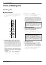
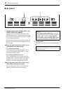
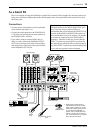
Input/output panel
1
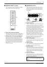
Hi-Z, Lo-Z input jacks
These are the input jacks for channels 1–4. By
using the PAD switches (control panel
5
) you
can connect any of the jacks to a wide range of
sources from mics to line level devices (synthesiz-
ers or rhythm boxes etc.). The Lo-Z jacks can
provide +15 V phantom power, allowing you to
use condenser microphones.
Both Hi-Z and Lo-Z are balanced, and are com-
patible with microphones of output impedance
50–600
Ω
or line level devices of 600
Ω
. The nom-
inal input level is –40 dB – –10 dB for the Hi-Z
jacks, and –50 dB – –20 dB for the Lo-Z jacks.
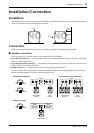
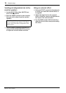
Pin connections for the Hi-Z and Lo-Z jacks are
as follows.
2
MIC, LINE, INST input jacks
These are the input jacks for channels 5–6.
Microphones can be connected to the MIC jacks,
and stereo line level devices (such as synthesizers
or rhythm boxes) can be connected to the LINE
jacks.
The MIC jacks are balanced, and are compatible
with microphones of output impedance 50–
600
Ω
.
The LINE
1
&
2
jacks are unbalanced, and are
compatible with line level devices of 600
Ω
output
impedance. These two input jacks can be used
simultaneously.
Nominal input level is –50 dB for the MIC jacks
and –10 dB for the LINE jacks.
INST 1 & 2 jacks are unbalanced, can be used
simultaneously, and their high input impedance
makes them ideal for use with instruments such
as electric-acoustic guitar and electric bass. They
can also be used with line-level sources, such as
synthesizers and drum machines. Nominal input
level is –30 dB.
3 Effect output jack (EFFECT OUT)
The input of an external effect such as a delay or
echo can be connected to this jack.
The signal adjusted by the EFFECT control of
each channel will be sent to the EFFECT bus, and
output from this jack.
The nominal output level and impedance are
+4 dB/10 kΩ.
4 Foot switch jack (FOOT SW)
A separately sold Yamaha FC5 foot switch can be
connected to this jack. If a foot switch is con-
nected to this jack, you can use your foot to
switch the built-in digital effect on/off.
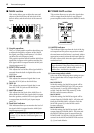
INPUT OUTPUT
MONITOR
MAIN
AUX IN
REC
OUT
TAPE
IN
EFFECT OUT
FOOT SW
1
2
11
22
1
2
LINEHi-Z INST
MIC MICLo-Z
Hi-Z
Lo-Z
Hi-Z
Lo-Z
Hi-Z
Lo-Z
SEE REAR PANEL CAUTION
21
5 6
43
EEEngine
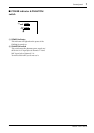
Lo-Z jacks
(XLR type)
Hi-Z jacks
(TRS phone jacks)
Pin 1: ground Sleeve: ground
Pin 2: hot (+) Tip: hot (+)
Pin 3: cold (–) Ring: cold (–)
Note: It is not possible to simultaneously use
both the Hi-Z and Lo-Z inputs of a given chan-
nel. For each channel, use only one of the inputs
as appropriate for the input source.
Phantom power is switched on/off in simulta-
neously for the Lo-Z jacks of channels 1–4 and
the MIC jacks of channels 5–6. For this reason,
any devices other than condenser microphones
must be connected to the Hi-Z or LINE jacks if
the PHANTOM switch (control panel L) is on.
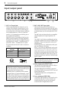
GND
RST
+-
GND
+-
Note: It is possible to simultaneously use both
the MIC and LINE inputs for channel 5, and the
MIC and INST inputs for channel 6.