


10
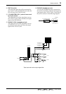
Front and rear panel
—Owner’s Manual
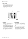
Master controls
■
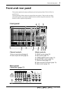
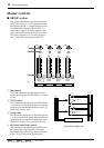
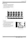
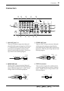
GROUP section
This section individually controls the output sig-
nal of GROUP buses 1–4. The signal that passes
through the GROUP 1–4 output channels can be
sent individually from the GROUP OUT 1–4
output jacks (page 20,
D
in the connector sec-
tion), and can also be sent to the ST bus or PFL/
AFL bus by using the TO ST switch (group sec-
tion
2
) and AFL switch (group section
4
).
1
PAN control
This knob adjusts the left/right position when
sending the signal of each GROUP bus 1–4 to the
ST bus.
2
TO ST switch
This switch sends the signal of each GROUP bus
1–4 to the ST bus. When the switch is on, the sig-
nal that has passed through the PAN control (1)
will be sent to the ST bus.
3 Group fader
This adjusts the output level of each GROUP bus
1–4. The position of the group fader will affect all
signals that are sent from the GROUP bus to the
GROUP OUT jacks, ST bus, and PFL/AFL bus.
4 AFL (after-fader listen) switch
This switch sends the signal of the GROUP bus to
the PFL/AFL bus. If this switch is on, the after-
fader signal of the GROUP bus can be monitored
in the C-R OUT jacks or the PHONES jack.
Group section signal flow
TO ST
PAN
AFL
10
5
0
5
10
15
20
30
40
RL
TO ST
PAN
AFL
10
5
0
5
10
15
20
30
40
RL
TO ST
PAN
AFL
10
5
0
5
10
15
20
30
40
RL
TO ST
PAN
AFL
10
5
0
5
10
15
20
30
40
RL
GROUP 1 GROUP 2 GROUP 3 GROUP 4
1
2
3
4
PFL/AFL
LR
GROUP
ST
RL
4321
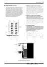
TO ST
AFL
Same as GROUP OUT 1-2
GROUP OUT 3-4:
to Meter
GROUP OUT 1
PA N
TO ST
AFL
to Meter
GROUP OUT 2
PA N