


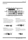
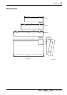

Connectors 19
—Owner’s Manual
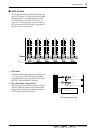
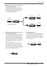
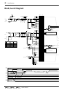
9 INSERT I/O jacks 1–20 {1–12 on the GF16/
12, 1–8 on the GF12/12}
These are TRS phone input/output jacks for
inserting external effect processors between the
EQ and channel fader of a monaural input chan-
nel. Nominal level is 0 dB. The pin wiring is
shown in the following diagram.
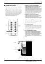
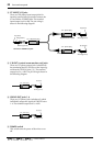
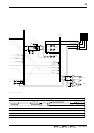
0 INPUT B jacks 21–24 {13–16 on the GF16/
12, 9–12 on the GF12/12}
These are phono input jacks (unbalanced) for the
stereo input channels. Nominal level is the same
as the INPUT A jacks (6). On the stereo input
channels, you can make connections both to the
INPUT A jacks (6) and the INPUT B jacks (0),
and use the A/B switch (page 8, 1 in the stereo
input channel section) to select whether INPUT
jack A or B will be used.
Be aware that in the case of the INPUT B jacks,
the channel cannot be used as a mono input
channel by inserting a plug only into 21L and
23L. (If only 21L or 23L are connected, the signal
will be sent only to the left channel.) The pin wir-
ing is shown in the following diagram.
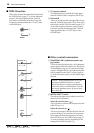
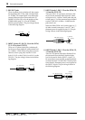
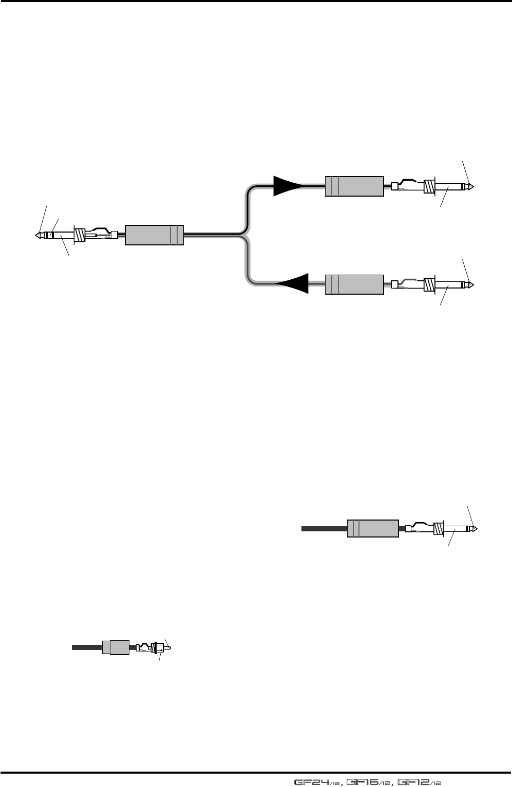
A AUX RETURN jacks 1/2
These are 1/4" phone input jacks (unbalanced)
for connecting the stereo output of external effect
processors, etc. The nominal level is +4 dB. If
inputting a monaural signal, connect a plug only
to the 1L or 2L jack. The pin wiring is shown in
the following diagram.
1/4" phone plug
1/4" phone plug
1/4" TRS phone plug
To processor’s input
From processor’s output
Connect to INSERT I/O jack
Tip (send)
Tip (send)
Ring (return)
Sleeve (ground)
Sleeve (ground)
Tip (return)
Sleeve (ground)
Phono plug
Tip
Sleeve
1/4" phone plug
Tip (send)
Sleeve (ground)