


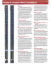
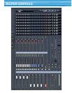
■ Inputs
The M3000A has 56, 40 or 24 mono and
4 stereo input channels with balanced
XLR-type microphone/line inputs. Phantom
power is independently switchable for all
mono inputs, providing direct compatibility
with high-performance phantom-powered
condenser microphones and DI boxes.
Stereo line sources can be directly
connected to either of 4 stereo input
channels (a total of eight inputs) via
switchable “A” or “B” inputs: the “A” inputs
are balanced XLR type connectors, and
the “B” inputs are standard RCA pin jacks
type for compatibility with the widest
possible range of line sources.
■ Channel Insertion
Insert send/return patch points are
included on all mono channels for conven-
ient insertion of compressor/limiters (a
must for top-quality vocal sound), equaliz-
ers, or any other outboard equipment you
might need to apply to individual chan-
nels.
■ Input Controls & Level Matching
Gain trim controls with a 44dB range on
all mono inputs, and independent 40dB
gain controls for the A and B inputs on the
stereo channels, facilitate optimum level
matching with a wide range of sources.
The mono inputs additionally feature 26dB
pad switches and phase switches for easy
input phase correction.
■ Filters & Flexible 4-band
Channel EQ
All mono channels feature a switchable
high-pass filters, sweepable from 20 Hz to
400 Hz to effectively eliminate rumble and
other low-frequency noise. The mono
channels also feature a very flexible 4-
band equalizer which provides sweepable
frequencies for all four bands as well as
switchable bandwidth for the HI MID and
LO MID bands. The stereo channels offer
fixed-frequency 4-band equalization with
switchable HI MID and LO MID bandwidth.
EQ bypass switches are provided on all
channels so equalization can be punched
in or out as required without having to
change settings.
■ Eight Group/Aux Sends
The M1 through M8 “Mix Send” controls
feed the M3000A console’s unique GA
Diversity system. When a FIX/VAR switch
in the master section is set to the “VAR”
position, the corresponding pair of send
controls (1/2, 3/4, 5/6, or 7/8) function as
auxiliary sends: i.e. the send control
adjusts the level of the signal sent to the
corresponding mix buss, and the send
switch (M1 … M8) simply turns the
corresponding send on or off. If a FIX/VAR
switch is set to the “FIX” position, the
corresponding send controls then function
as post-fader group sends: The send
control is bypassed, and the send switch
functions as a group assign switch. For
even further flexibility the M1 through M4
control group and the M5 through M8
control group can be independently
switched for pre- or post-fader send.
■ Eight Aux Sends
The M9 through M12 controls function
as mono auxiliary sends, feeding the
corresponding mix buss. The remaining
four sends are configured as dual stereo
sends (13/14 and 15/16) with balance
controls. These controls can be switched
to receive the pre- or post-fader signal in
groups of four (i.e. the four mono sends as
one group and the two stereo sends as the
second group).
■ Stereo Assign & Pan/Balance
Controls
Stereo assign switches and pan
controls on each mono channel - stereo
assign switches and balance controls on
the stereo channels - assign the corre-
sponding channel signal to the console’s
stereo buss.
■ 3-point Level Indicators
All mono and stereo channels feature 3-
point level indicators for accurate monitor-
ing of pre-fader signal levels. SIGNAL,
NOM (nominal), and PEAK LEDs provide a
broader “view” of channel signal levels
than the usual one- or two-LED indicators.
■ Channel Faders, Pre-fader
Listen, & Channel ON Switches
Smooth, noise-free 100-mm linear
faders make it easy to set up the optimum
balance between channels, while PFL
(Pre-Fader Listen) switches allow conven-
ient solo monitoring of the channel’s pre-
fader signal. All channels additionally
feature channel on switches that can be
used to switch the channel signal into or
out of the mix without changing any other
settings.
■ VCA Group Assign
A feature taken directly from Yamaha’s
industry-leading PM3500 series mixing
consoles, VCA grouping allows channels
to be grouped and assigned to any of
eight VCA master faders in the master
section without actually re-routing the
channel signals, thus maintaining unsur-
passed signal quality. The VCA GROUP
switches (1 … 8) next to each channel
fader assign the channel to the corre-
sponding VCA master fader. The high-
performance VCAs (Voltage Controlled
Amplifiers) are located immediately before
the channel faders, and thus function in
essentially the same way as the channel
faders themselves, adjusting the level of
the channel’s post fader signal.
MONO INPUTS
STEREO INPUTS
MONO & STEREO INPUT CHANNELS