


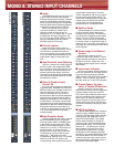
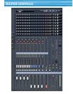
■ GA Diversity FIX/VARI Switches
The core of the GA console’s innovative GA
Diversity system, these switches determine
whether the corresponding pairs of sends on
the input channels - M1 through M8 - function
as auxiliary or group sends (see “Eight Group/
Aux Sends” for more details).
■ Mix Buss Masters
The first eight mix buss master strips - M1
through M8 - receive either the aux signal or
the group signal from the channel sends,
depending on the setting of the corresponding
GA Diversity FIX/VARI switch. Mix masters M9
through M16 receive the auxiliary signal from
the corresponding channel send controls.
While M9 through M12 have independent
controls, M13 through M16 are configured as
dual stereo masters (M13/14 and M15/16).
Each of these mix master control groups has
its own linear fader as well as a “TO STEREO”
switch and pan control (balance controls on
the stereo pairs) which assign the mix buss
signal to the console’s stereo buss. “TO
MATRIX” switches assign the corresponding
mix master signal to the console’s matrix mix
(below). The mix buss master strips AFL (After-
Fader Listen) switches for convenient solo
monitoring, and ON/EDIT switches equivalent
to those on the input channels.
■ Mix Outputs, Inserts & Sub Inputs
All 16 mix busses feed balanced XLR type
outputs. They also feature insert patch points
for auxiliary signal processing, as well as sub
inputs which allow external line-level signals to
be individually added to the mix signals as
required.
■ Dual Stereo Masters
The stereo buss feeds two stereo output
pairs: stereo A and stereo B. The main linear
stereo fader feeds the balanced stereo A
outputs, with AFL listen capability and a “TO
MATRIX” routing switch. The stereo B signal
feeds a second balanced output pair via the
rotary stereo B level control.
■ Submix Matrix
The matrix mix concept was a Yamaha
innovation which has virtually become an
industry standard in professional audio
consoles. The M3000A features a 20 x 8
matrix mix which allows the 16 mix buss
signals, the stereo A signals, and the matrix L
and R sub input signals to be mixed to eight
balanced outputs for extra stage monitor
mixes, zoned speaker mixes, or just about any
type of mix the job requires. All eight matrix
mixes include mix on/off switches and AFL
switches.
■ VCA Group Masters
The eight VCA group masters include a 100-
mm linear fader which controls the assigned
channel VCAs (see “VCA Group Assign”), a
VCA mute switch which mutes the assigned
channel VCAs, and a nominal level LED.
A VCA EXTERNAL I/O connector allows two
M3000A consoles to be connected - or an
M3000A can be connected to any other VCA-
compatible Yamaha console such as the
PM3500 - for linked VCA group control.
■ 128 MIDI Scene Memory/
8 Mute Groups
The M3000A console the channel, mix
master, and stereo A on/off functions are
electronically controlled by a microcomputer
and MIDI interface. Up to 128 mute “scenes”
can be stored in memory and recalled either
via the panel controls or an external MIDI
device. Eight DIRECT RECALL switches can be
used for instant recall of the most often-used
scenes, while others can be recalled via the
numeric keys. The memory contents can be
checked and edited at any time without
actually affecting the mix.
A utility function allows the DIRECT RECALL
switches to be re-assigned for “mute group”
switching, which allows mutiple mute scenes
to be engaged at the same, adding the mute
assignments for all active scenes.
In addition to recalling complete scenes,
external MIDI control can be used to individu-
ally turn the applicable channels and busses
off or on as required. A MIDI sequencer or
computer, for example, could be used for
complete mute automation. And since the
M3000A also transmits MIDI program change
messages whenever a scene is recalled, it can
be linked to MIDI-controllable signal proces-
sors so that appropriate effects are recalled
automatically. Furthermore, scene data can be
dumped to a MIDI data recorder or other
storage device for long-term storage.
■ Flexible Monitoring & Metering
Convenient monitoring is provided by
balanced monitor outputs and phones output
with independent level controls. In addition to
monitoring the stereo buss, the monitor signal
can be derived from either of the M3000A’s
two 2TR IN tape inputs. There’s also a L+R
switch which sums the left- and right-channel
signals for mono monitoring.
A total of 12 large, illuminated VU meters
with built-in peak-reading LEDs provide
accurate visual level monitoring. Eight of these
can be switched to display the levels on mix
busses 1 through 8 or 9 through 16, or the
levels at the eight matrix outputs. The remain-
ing four display the stereo A L and R and cue L
and R levels.
■ Oscillator/Talkback Module
In addition to a panel microphone connec-
tor, level control and switch for talkback, the
M3000A includes a versatile oscillator which
provides pink noise as well as 10 kHz, 1 kHz,
and 100 Hz sine waves for precise calibration
and testing. The oscillator signal is assignable
to the mix busses in pairs or groups of four
(1/2, 3/4, 5/6. 7/8, 9 through 12, and 13
through 16) and/or the stereo buss.
■ Lamp Connectors
Connectors for up to three Yamaha LA1800
console lamps are provided on the M3000A
rear panel.
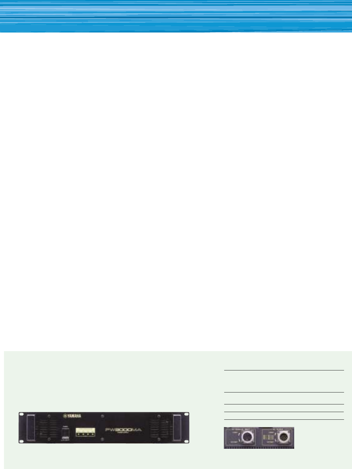
PW3000MA Power Supply
A newly developed, high-performance PW3000MA power supply unit is available as an
optional accessory for the M3000A mixing console. Two PW3000MA units can be
parallel connected so that if one fails the other will automatically take over — with no
need for any extra automatic switchover equipment.
Rear Panel
PW3000MA Specifications
Power consumption
U.S. and Canadian model: 120V AC,60Hz / 500W 600 VA
European model: 230V AC, 50Hz/ 500W
Australian model: 240V AC, 50Hz/ 500W
Dimensions (H × D × W)
103.5 × 455 × 480 mm (4-1/16” × 17-5/16” × 18-7/8”)
Weight 15kg (33.1 Ibs)
Accessory Connecting cable (1m) × 1