


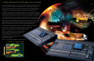
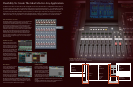
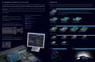

Elegant, Efficient, and Eminently Practical
Everything you need for hands-on mix control is right where you need it. The PM5D’s physical control surface offers direct
access to all of the major functions you’re likely to need for just about any real-world application.
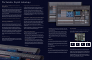
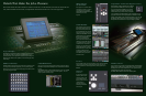
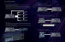
Input Patching
Although physical input jacks 1 through 48 on
the rear panel of the PM5D are connected to
the corresponding internal channels by
default, digital patching provides total
assignment freedom. You won’t have to run
around to physically re-patch cables whenever
you need to reconfigure the system. On-screen
patch displays allow the system’s inputs and
outputs to be patched to appropriate I/O points and you can also assign and display channel
names for easy identification. Patch setups you might want to use again can be stored in the
patch library for instant recall at any time.
Mic Preamp Controls
While the PM5D’s manual microphone preamplifiers have physical phantom power, pad, gain,
and insert switching controls, the PM5D-RH’s recallable mic preamplifiers allow access to the
same parameters via the console’s encoders and software. Both models offer peak and signal
indication LEDs for easy visual input level monitoring.
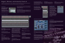
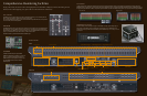
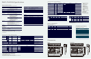
Channel Strip Controls
Layer Select Keys
The CH 1-24 and CH 25-48 layer select keys determine whether
the console’s 24 physical mono channel strips control channels 1
through 24 or 25 through 48.
ENCODER ON Key (Upper)
Turns encoder assigned functions on or off. For example, it
can be used to switch the send to the mix bus on or off.
PRE Key
Selects pre or post mix send.
Rotary Encoder
The function of the channel strip rotary encoders is
determined by the ENCODER MODE keys. They can function
as mix send level controls, channel pan controls, head
amplifier gain or attenuation controls, or as alternate-layer
level controls.
TO STEREO, GATE, and COMP Indicators
The TO STEREO indicator lights when the channel signal is
feeding the stereo mix bus. The GATE indicator lights when
the channel gate is on, lights dimly during gate attack or
decay, and goes out when the gate is open. The COMP
indicator lights when the channel compressor is applying
gain reduction, lights dimly during compressor attack or
decay, and goes out when no gain reduction is being applied.
SEL Key
Assigns the corresponding channel to the console’s
SELECTED CHANNEL control section and to the built-in LCD
display. The SEL keys can also be used to assign channels as
stereo pairs.
Channel Name Display
This 4-character display shows the assigned name for the
corresponding channel. The name dims when the channel is
muted.
CH ON Key (Lower)
Turns the corresponding input channel on or off.
Meter
A 6-point LED meter displays the channel input level.
DCA Indicators
The console’s input channels can be assigned to any of 8
DCA. The console’s input channels can be assigned to any of
8 DCA faders. The DCA LEDs indicate the DCA faders to which
the channel is assigned.
MUTE Indicators
Input channels can be assigned to eight mute groups for
versatile mute control. The MUTE LEDs indicate the mute
groups to which the corresponding channel is assigned.
RCL and MUTE SAFE Indicators
The RCL SAFE LED lights when the channel is set to the recall
safe mode so that it will not be affected by scene recall
operations. The MUTE SAFE mode prevents the channel from
being affected by mute group operations.
Channel Fader
These very smooth and quiet 100mm motorized faders
control and display the channel input level, or the send level
to the selected mix bus when the FADER FLIP mode is on.
CUE Key
Sends the channel signal to the cue bus for monitoring
according to the currently selected cue mode: LAST CUE, MIX
CUE, or SOLO and various function settings.
Stereo Input Channels
The stereo input channels are essentially the
same as the mono input channels, except that
they have stereo level meters, and ST IN 1-4 and FX
RTN 1-4 keys that assign the strips for stereo input
channel or stereo effect return operation.
ENCODER MODE &
FADER FLIP Keyes
The ENCODER MODE keys determine the
function of the rotary encoders at the top of the
console’s channel strips: send level to each of 24
mix buses, channel pan, Input gain of the
recallable head amps in the PM5D-RH (or
connected remote recallable head amplifiers) or
attenuation after A/D conversion, and input fader
level of alternate (unselected) layer.
The FADER FLIP key swaps the functions
assigned to encoders and faders. For example, if
you engage the FADER FLIP key when MIX SEND
is selected, the channel-strip faders adjust the
mix send level while the encoders adjust the
channel input level.
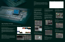
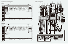
SELECTED CHANNEL Controls
EQUALIZER & HPF
A flexible 4-band equalizer section with high and low bands switchable for shelving or peaking
response, variable frequency and Q on all bands, and an independent variable-frequency HPF.
Since 8-band EQ is provided for output channels, UPPER and LOWER keys are provided to
assign control to the upper or lower four bands.
NOISE GATE
Extremely versatile noise gate provides effective noise suppression, ducking, and other gate
functions. Extensive control is provided with independent threshold, range, attack, hold, decay
parameters, keyins and keyin filters.
COMPRESSOR
A full-featured compressor/expander/compander module with independent threshold, range,
attack, release, knee and ratio parameters. Like the noise gate section, the compressor section
includes a six-segment gain reduction meter for convenient visual monitoring.
DELAY
Turns the channel delay on or off, and sets the delay time
from 0 to 1,000 milliseconds for the selected input channel.
GROUP
This section controls channel to DCA and MUTE group
assignments. The DCA keys assign the currently selected input
channel to one or more of the DCA faders, while the MUTE
keys assign the currently selected input channel to one or
more of the eight available mute groups. The GROUP section
also includes RECALL SAFE and MUTE SAFE assign keys that
engage or disengage recall safe and/or mute safe status for
the currently selected input channel.
CHANNEL SELECT
This section can be used to select the channel to which the
SELECTED CHANNEL controls will apply. COPY and PASTE
function are also included, making it easy to copy all
parameters from one channel to any other channel.
GAIN/ATTENUATION/Ø
When the GAIN/ATT key is on the encoder adjusts the gain of
a recallable microphone preamplifier patched to the input of
the selected channel. When the GAIN/ATT key indicator is off
the encoder adjusts attenuation for the selected channel. The
Ø key inverts the phase of the selected channel.
STEREO
The STEREO section allows the currently selected channel
signal (input, stereo input, effect return, mix) to be routed to
the stereo bus with pan control.
INPUT PATCH