


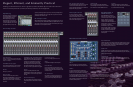
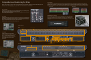
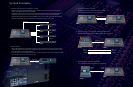

Input Connectors
INPUT 48
ST IN 8
CASCADE IN 32
SLOT 64
2TR IN DIGITAL* 6
2TR IN ANALOG* 4
Internal Input
FX OUT* 16
Output Connectors (Fixed)
4 STEREO*
24 MIX
8 MATRIX
3 MONITOR OUT
2 CUE OUT*
Internal Output
16 FX IN*
Output Connectors (Assignable)
64 SLOT
32 CASCADE OUT
6 2TR OUT DIGITAL*
Mixer Input
4 48 CH
8 ST IN*
92 INSERT IN
8 FX RTN*
Mixer Output
STEREO* 4
MIX 24
MATRIX 8
MONITOR OUT 3
INSERT OUT 92
DIRECT OUT 56
OSC OUT 1
TB OUT 1
INPUT
PATCH
OUTPUT
PATCH
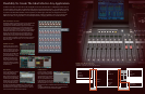
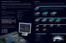
Flexibility To Create The Ideal Mix For Any Application
In addition to dual stereo mix buses that can be used together for LCR send, the PM5D offers 24 independent mix buses that you
can use for submix, auxiliary, effect, or just about any other type of send your application requires … all with master mix control
as well as individual mix send level control from all available inputs. And they have 8-band EQ, compression, and delay that you
can control via the SELECTED CHANNEL controls to optimize your submix signals. And if that isn’t enough, there’s also an 8-
output matrix mix for the mix and stereo buses (also equipped with EQ, compression and delay!). Once you’ve created all the
submixes you need, you can group them, as well as the input channels, by assigning them to the very versatile DCA faders.
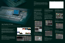
MIX Send/Master Controls
Independent MIX control blocks are provided for the console’s 24 mix buses. When the MIX SEND
key is engaged the MIX encoders adjust the send level from the selected channel to the
corresponding mix buses. When the MIX MASTER key is engaged the encoders function as master
level controls for the corresponding mix buses. You can still use the channel-strip encoders to
adjust mix send level by using the MIX SEND SELECT keys to specify the destination mix bus.
The MIX blocks also include ON keys to turn the corresponding send on or off, TO STEREO and
TO MTRX LEDs to indicate assignment to the stereo and matrix busses, PAIR LEDs that indicate
paired mix sends, and CUE and SEL keys that assign the corresponding MIX signal to the
SELECTED CHANNEL controls when the MIX MASTER mode is engaged. When an odd-even
numbered pair of mix bus sends is assigned as a stereo pair, the odd-numbered encoder
functions as a pan/balance control while the even-numbered encoder sets the send level for the
pair. The MIX controls can be assigned to DCA groups 7 and 8, so a pair of DCA assignment
indicators is also provided.
MATRIX Controls
The MATRIX controls comprise an 8-channel
submix matrix from the mix and stereo buses.
Each matrix module features a level encoder,
ON key, CUE key, and SEL key which assigns that
channel to the SELECTED CHANNEL controls.
Like the MIX bus controls, the MATRIX controls
can be assigned to DCA groups 7 and 8, so a
pair of DCA assignment indicators is provided.
PAIR LEDs indicate paired matrix controls.
When an odd-even numbered pair of matrix
controls is assigned as a stereo pair, the odd-
numbered encoder functions as a pan/balance
control while the even-numbered encoder sets
the send level for the pair.
DCA Faders
Any input or output channels can be assigned to
any of the console’s eight DCA faders for
convenient grouping. Each DCA strip also
includes a four-character name display as well as
MUTE and CUE keys for convenient muting and
cue monitoring of the corresponding DCA signal.
The faders can also be used to control individual
bands of the internal graphic equalizers. In fact,
you can assign a variety of functions to the DCA
faders that can be instantly recalled via the FADER MODE keys. You could, for example, assign
input channel level control to the DCA faders so you have simultaneous control of 32 channels
instead of the normal 24. Or you could assign mix master levels, matrix levels … whatever you
need to work in the most productive, efficient manner for the job at hand.
STEREO Faders
The master stereo faders control the output
from the console’s STEREO A and STEREO B
buses. In addition to the faders the STEREO
strips include channel ON keys, TO MTRX and
COMP LEDs, CUE keys, and SEL keys which
assign the corresponding STEREO bus signal to
the SELECTED CHANNEL controls. The STEREO
OUTPUT block also features RECALL SAFE and
MUTE SAFE LEDs similar to those on the input
and output channels, and DCA 7 and 8 LEDs that indicate assignment to the corresponding
DCA faders.
The STEREO B strip additionally features a MONO key that sums the STEREO B channels to a
mono signal that can serve as the center channel for LCR configurations.
PM5D Mixer Block Overview
• All Numbers counted in monaural *Used in Stereo pairs.
• Model PM5D is equipped with Insert I/O's along with Input Connectors.
MATRIX/ST ROUTING
MIX to MATRIX VIEW 1
DCA GROUP ASSIGN (In) DCA GROUP ASSIGN (Out)
MIX to MATRIX VIEW 2