


10
Front and rear panel
EMX88S/EMX68S—Owner’s Manual
Front and rear panel
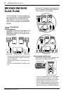
Control panel
■
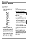
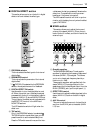
Channel section
Use these controls to adjust factors such as the
equalization, (frequency response), volume,
effect and monitor output level for the input sig-
nal to each channel.
1
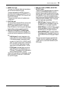
Equalizer controls (HIGH, MID, LOW)
This is a 3-band equalizer that adjusts the high
frequency range, mid frequency range, and low
frequency range of each channel. Response is flat
when the knobs are in the “
▼
” position. Rotating
it toward the right will boost the corresponding
frequency band, and rotating it toward the left
will cut it.
The base frequency (or center frequency), range
of boost or cut, and equalizer type of each band
are as follows.
HIGH: 10 kHz ±15 dB shelving type
MID: 2.5 kHz ±15 dB peaking type
LOW: 100 Hz ±15 dB shelving type
2
MONITOR control
For each channel, this controls the amount of sig-
nal that is sent to the MONITOR bus.
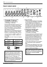
The signal of the MONITOR bus is sent to the
MONITOR jacks (input/output panel
7
).
3
EFFECT control
For each channel, this controls the amount of sig-
nal that is sent to the EFFECT bus.
The signal of the EFFECT bus is sent to the built-
in digital effect, and to the EFFECT OUT jacks
(input/output panel
4
).
4
PAN control (BAL/PAN control for CH7/8
(EMX88S), CH5/6 (EMX68S))
This knob adjusts the stereo image (L/R) for each
channel. Adjust for equal volume on left and
right with a sound source input to the CH7 and 8
(EMX88S), CH5 and 6 (EMX68S) LINE connec-
tors (L/R).
5
LEVEL control
This adjusts the output level for each channel.
6
PAD switch (1–6 (EMX88S) only, 1–4
(EMX68S) only)
This switch attenuates the input signal by 30 dB.
When connecting a line level device to channels
1–6 (EMX88S), 1–4 (EMX68S), or if the mic
input is distorted, turn this switch on (the
pressed-in position).
1
2
3
4
5
6
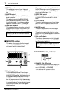
Note:
The signal is sent to the MONITOR bus
from a location before the level control (
5
) of
each channel. This means that it will not be af-
fected by the setting of the Level control.
Note:
The signal is sent to the EFFECT bus
from a location after the level control (
5
) of
each channel. This means that the amount of
signal that is sent to the EFFECT bus will be af-
fected not only by the setting of the effect con-
trol, but also by the setting of the level control.