


RS500/RS700 Owner’s Manual 3
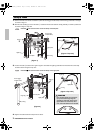
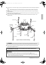
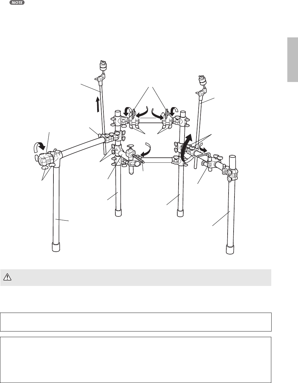
5. Loosen the bolt r, and as shown in Figure 3, raise up the cymbal holder located on the left. Following this, retighten the
bolt r.
•When tightening the bolt, ensure that the black sleeve is positioned inside the clamp’s mounting hole.
6. Loosen the bolts t, and as shown in Figure 3, rotate upward the cymbal holder located on the right. Following this,
retighten the bolts t.
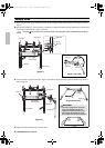
7. Loosen the bolts e and open up the pipe q to position it as shown in Figure 3. Then, rotate the snare clamp rod to the
position shown in Figure 3. Retighten the bolts e.
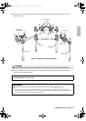
8. Loosen the bolts of the tom holders and rotate the three tom holders into the positions shown in Figure 3. Then,
retighten the bolts.
9. Loosen the bolts y securing the drum trigger module clamp in place, position the clamp with its flat surface facing
upward, and then retighten the bolts y.
CAUTION
• Take special care when handling the tom holders in order to avoid injuring yourself with their sharp ends.
For information about the next steps such as assembling Yamaha Electronic Drum Set, refer to
“Assembly Manual” in the Pad Set.
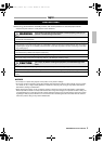
Specifications
External dimensions: 1196 (W) x 528.3 (D) x 812.3 (H) mm (Standard Assembly) Weight: 11 kg
* Specifications and descriptions in this Owner’s Manual are for information purposes only. Yamaha Corp. reserves the right to
change or modify products or specifications at any time without prior notice. Since specifications, equipment or options may not be
the same in every locale, please check with your Yamaha dealer.
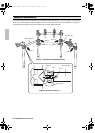
[Figure 3: Example of standard assembly]
Bolts e
Tom holder
Tom holder
Left leg
Right leg
Drum trigger
module clamp
Right pillar
Left pillar
Cymbal holder
Cymbal holder
Snare clamp rod
Bolts r
Bolts t
Bolts
Pipe q
Bolts y
5
6
7
8
8
8
8
8
9
rs500_700_en_1224.fm Page 3 Friday, December 24, 2010 9:15 AM