


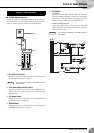
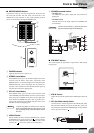
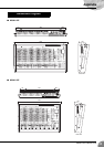
Front & Rear Panels
MG32/14FX, MG24/14FX
21
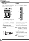
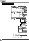
7 ST INSERT I/O (L, R) Jacks
These are balanced TRS (tip, ring, sleeve) phone-type bidirec-
tional jacks. You use these jacks, for example, to connect to an
external effector, submixer, or other such device.
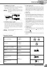
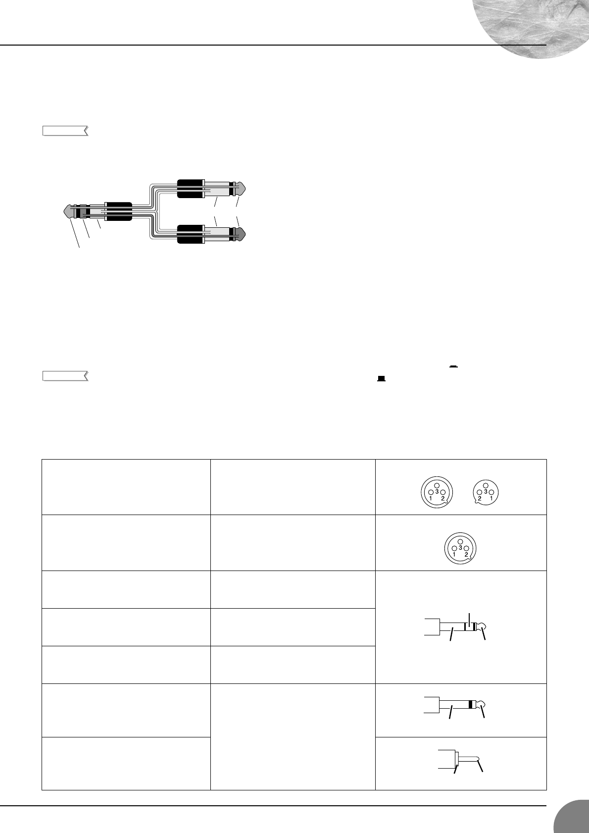
Connection to an INSERT I/O jack requires a spe-
cial separately-sold insertion cable such as illus-
trated below.
8 ST SUB OUT Jacks (L and R)
These are impedance-balanced phone output jacks. These jacks
output a clone of the mixed stereo signal from the ST bus. The
level for this output is adjusted by the ST SUB OUT control in
the Master Control block (see page 13). You would typically
use these jacks to connect to an external mixer or a supplemen-
tary SR system.
The ST master fader does not operate on the sig-
nals from these jacks.
9 ST OUT Jacks (L, R)
These are balanced XLR output jacks. These jacks output the
mixed stereo signal from the mixer’s ST bus. The level for this
output is adjusted by the ST master fader in the Master Control
block (see page 13). You typically use the jacks to connect to
your main output, such as to the power amplifiers driving your
main speakers.
0 MONO Jack
This balanced XLR input jack outputs a monaural mix of the
stereo signal from the ST bus. The level for this output is con-
trolled by the MONO fader in the Master Control block (see
page 13). The output is a mix of the ST bus’s L and R signals.
A FOOT SWITCH TAP Jack
This phone input jack is for connection to a foot switch, for use
with the TAP DELAY feature. If you connect the (separately
sold) YAMAHA FC5 foot switch to this jack and then set inter-
nal EFFECT 2 to [16] TAP DELAY, you can use the foot
switch (as an alternative to the TAP button) to set the delay.
The mixer will automatically set the delay to the interval
between the last two taps.
B POWER Switch
Use this switch to turn the mixer’s power ON and OFF. Press
the switch in to set the power on ( ), and press again to set
the power off ( ).
C AC IN Connector
Connects to the socket end of the AC power cord included with
the mixer.
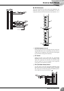
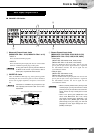
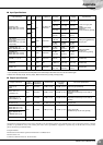
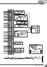
Connector Polarities
*These jacks also accept connection to monaural phone plugs. If you use monaural plugs, the connection will be unbalanced.
NOTE
To the INSERT I/O jack
To the input jack of the external processor
To the output jack of the external processor
Ring
Sleeve
Tip
Sleeve
Tip
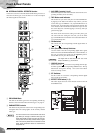
NOTE
INPUT A, ST OUT, MONO
Pin 1: Ground
Pin 2: Hot (+)
Pin 3: Cold (–)
MIC (Talkback)
Pin 1: Ground
Pin 2: Hot (+)
Pin 3: Ground
INPUT B, GROUP OUT, AUX SEND (1 to 6),
EFFECT SEND (1, 2), ST SUB OUT*
Tip: Hot (+)
Ring: Cold (–)
Sleeve: Ground
INSERT I/O,
GROUP INS I/O, ST INSERT I/O
Tip: Output
Ring: Input
Sleeve: Ground
PHONES
Tip: L
Ring: R
Sleeve: Ground
Stereo channel input jacks,
RETURN (1, 2)
Tip: Hot
Sleeve: Ground
Stereo channel input jacks,
2TR IN,
REC OUT
INPUT OUTPUT
INPUT
Ring
Sleeve Tip
Sleeve Tip
Sleeve Tip