


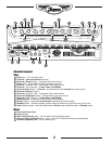

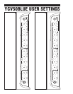


Channel 1
5
7
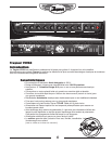
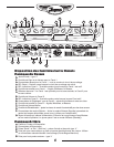
Channel 1 is the lead/overdrive channel and is
selected in one of two ways, via the Channel Select
switch on the control panel, or via the Channel Select
button on the supplied footswitch* pedal. A Yellow
LED located next to the Channel 1 Volume control
illuminates when Channel 1 is active.
*Note: Plugging in the footswitch deactivates the panel-
mounted Channel and Boost controls.
Gain & Volume Controls
2
Channel 1 uses a Gain control in conjunction with a
Volume control to control the amount of tube-based
overdrive and volume. The Gain control is used to adjust
the amount of overdrive, while the Volume control allows
you to set the actual loudness of the amplifier.
Boost Switch
3
4
A boost circuit is included to help you achieve ‘a-bit-
more’ overdrive for leads. The boost can be selected
via the front panel switch or through the supplied
footswitch pedal. A Red LED illuminates to indicate
when the boost is active.
Channel 1 Tone Controls
6
The Treble, Bass, and Middle tone controls are used to help
you shape your sound. They are post-gain and pre-volume.
These are active only when Channel 1 is selected.
Channel 2
8
9
11
Channel 2 is the clean channel and thus has no Gain
control. In other respects the layout is the same as that
of Channel 1, with independent Volume and Treble,
Bass, and Middle tone controls. When channel 2 is
active the green LED located next to the Channel 2
Volume control is illuminated.
Brightness Switch
10
Channel 2 includes a Brightness switch that activates
a circuit to provide additional treble boost to help make
your tone sparkle.
Master Controls
Master Volume Control
12
The Master Volume control adjusts the overall volume
of the amplifier.
Reverb Control
13
The Master Control section also includes a rotary
Reverb control that adjusts the overall reverb level
for both channels. The YCV50 is equipped with
a long-style Accutronics® dual-spring reverb for
authentic vintage reverb.
Standby Switch & Indicator
14
15
This switch controls the high voltage power being supplied
to the tubes. This mode effectively keeps the tubes warmed
up when the amp is not in use. The large, jewel indicator on
the front panel glows Red when the amp is fully powered-
up and changes to Yellow when the high voltage circuit has
been turned off. Putting the amp into Standby mode (i.e.
during set breaks) shuts off the amplifier output stage and
effectively increases tube life by reducing wear on the tubes.
EFX / LINE Send & Return Jacks
18
The Send and Rtn jacks of the YCV50 allow convenient
use of an external effect unit. Simply connect a 1/4 inch
phone cable to the Send jack of the YCV50 and then
connect this cable to the Input of your effects unit. To send
the processed signal back to the YCV50, connect the
output of the effects unit to the Rtn jack of the YCV50.
The 1/4 inch TRS Send jack can be used as part of
an effects loop in conjunction with the Rtn jack. It can
also be used as a direct line out (preamp-out). The -
10dBu output is ideal for most guitar effects pedals and
professional signal processors. You can also use this
output to slave the YCV50 with another guitar amplifier
by plugging into the Rtn jack of the slave amplifier.
The 1/4 inch TRS Rtn jack can be used as your return
jack for your effects loop. It accepts an input signal that
is passed to the power amplifier, so it can be used as a
power amp in. The Master Control section regulates the
signal, so you can add Reverb as well as Presence.
Footswitch Jack
19
Connecting a footswitch to the 1/4 inch TRS Footswitch
jack deactivates the control panel mounted Channel
Select and Boost switches. These functions are then
activated exclusively by the pedal. The included
footswitch features dual-latching switches, each with a
separate LED indicator.
The switching is accomplished with internal relays
so there is no audiable noise flowing through the
footswitch cable. Footswitch-induced noise is never an
issue. The YCV50 is compatible with most aftermarket
latching dual-footswitch pedals.
External Speaker Jack/s
20
These under-the-chassis mounted 1/4 inch jacks
allow convenient connection of an 8-ohm external
speaker cabinet. If you disconnect the internal 12
inch Celestion® speaker, you can connect up to
two 8-ohm external cabinets.
3