20 en | Installing the Pendant Arm Wall, Corner, and Mast (Pole) Mounts AutoDome 800 Series HD PTZ Camera
F.01U.273.797 | 5.0 | 2012.08 Installation Manual Bosch Security Systems, Inc.
Table 2.1 Power Supply Box Connections
2.5 Route Power through Intermediate Power Supply Box
You may route the main power supply through a VG4-PSU1 (120 V transformer) or through a
VG4-PSU2 (230 V transformer) Power Supply Box before connecting the power to a VG4-PA0
(24 V, no transformer) Power Supply Box. The main issue with this configuration is that the 5-
pin power out connector from the VG4-PSU1 or VG4-PSU2 does not match to the 3-pin power
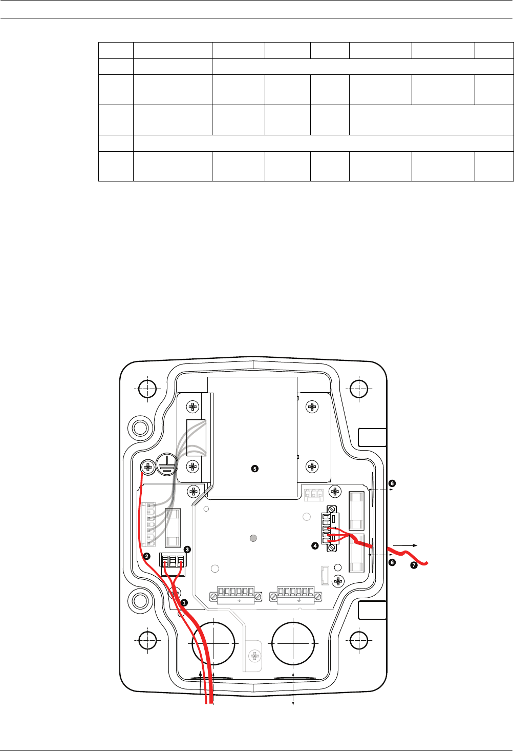
input of the VG4-PA0 power supply. The illustration below depicts:
– A VG4-PSU1/VG4-PSU2 Power Supply Box.
– The main power supply connected to the P101 connector and to the grounding screw.
– The 24 VAC power out wire connected to the P107 heater power connectors.
Figure 2.5 VG4-PSU1/VG4-PSU2 Power Supply Box
No. Connector Pin 1 Pin 2 Pin 3 Pin 4 Pin 5 Pin 6
Ground Grounding Screw
P101 115/230 VAC or
24 VAC Power In
Line NC Neutral
P105 Data/Audio Audio Audio Earth
Ground
Not Used
P106 Not Used
P107 24 VAC Power
(Arm Harness)
Dome
24 VAC
Dome
24 VAC
Earth
Ground
Heater
(24 VAC)
Heater
(24 VAC)
GND
+
-
ND
X
X
+
-
P1
P1
P107
XF102 XF103
XF101
5 4 3 2 1
1
2
10
(LED)
VG4-PSU1 / VG4-PSU2
HTR DOME
FUSE
FUSE)


