DM9161B
10/100 Mbps Fast Ethernet Physical Layer Single Chip Transceiver
7 Final
Version: DM9161B-12-DS-F01
January 31, 2008
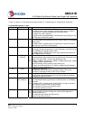
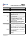
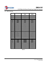
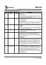
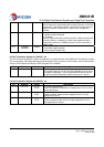
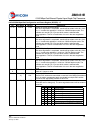
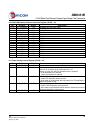
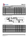
34 RXCLK
/10BTSER
O,
Z,
LI
(U)
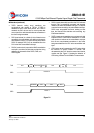
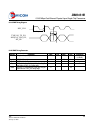
Receive Clock
The received clock provides the timing reference for the transfer of the
RXDV, RXD, and RXER. RXCLK is provided by PHY. The PHY may
recover the RXCLK reference from the received data or it may derive the
RXCLK reference from a nominal clock
25MHz in 100Mbps MII mode, 2.5MHz in 10Mbps MII mode, 10MHz in
10Mbps GPSI (7-Wired) mode
10BTSER only support for 10M mode; (power up reset latch input)
0 = GPSI (7-Wired) mode in 10M mode
1 = MII mode in 10M mode
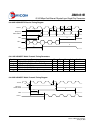
35 CRS
/PHYAD[4]
O,
Z,
LI
(D)
Carrier Sense Detect/ PHYAD[4]
Asserted high to indicate the presence of carrier due to receive or transmit
activities in half-duplex mode of 10BASE-T or 100BASE-TX. In repeater
mode or full-duplex mode, this signal is asserted high to indicate the
presence of carrier due to receive activity only
This pin is also used as PHYAD [4] (power up reset latch input)
PHY address sensing input pin
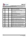
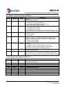
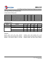
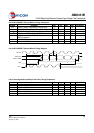
36 COL
/RMII
O,
Z,
LI
(D)
Collision Detection
Asserted high to indicate the detection of the collision conditions in
half-duplex mode of 10Mbps and 100Mbps. In full-duplex mode, this signal
is always logical 0
Reduced MII enable:
This pin is also used to select Normal MII or Reduced MII. (power up reset
latch input)
0= Normal MII (default)
1= Reduced MII
This pin is always pulled low except used as reduced MII
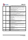
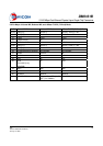
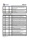
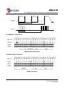
37 RXDV
/TESTMODE
O,
Z,
LI
(D)
Receive Data Valid
Asserted high to indicate that the valid data is presented on the RXD [0:3]
Test mode control pin (power up reset latch input)
0 = normal operation (default)
1 = enable test mode
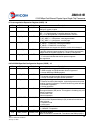
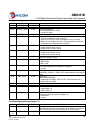
38 RXER/RXD[4]
/RPTR
O,
Z,
LI
(D)
Receive Data Error/The Fifth RXD Data Bit of the 5B Symbol
Asserted high to indicate that an invalid symbol has been detected
In decoder bypass mode (bypass BP4B5B), RXER becomes RXD [4], the
fifth RXD data bit of the 5B symbol
This pin is also used to select Repeater or Node mode. (power up reset
latch input)
0 = Node Mode (default)
1 = Repeater Mode
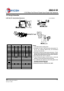
31 LEDMODE I LED MODE Select
Reference LED function description
0: support Dual-LED
1: Normal LED
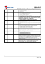
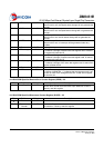
40 RESET# I Reset
Active low input that initializes the DM9161B.