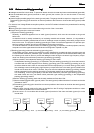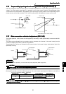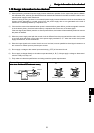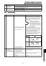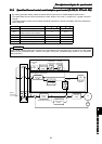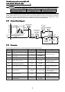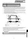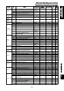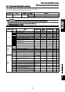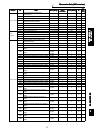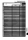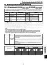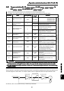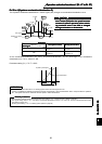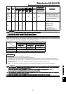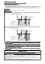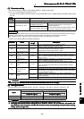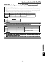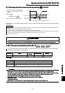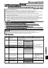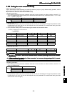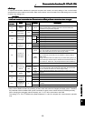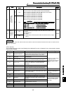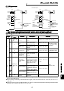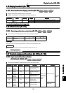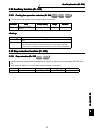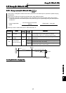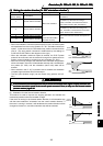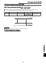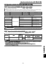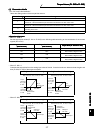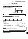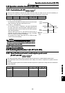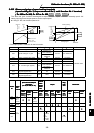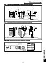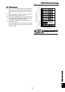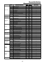
&RQGLWLRQDOSRVLWLRQFRQWURO3U
&RQGLWLRQDOSRVLWLRQFRQWURO3U&RQGLWLRQDOSRVLWLRQFRQWURO3U
&RQGLWLRQDOSRVLWLRQFRQWURO3U
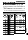
WR3U3UWR3U
WR3U3UWR3UWR3U3UWR3U
WR3U3UWR3U
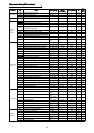
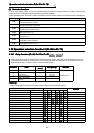
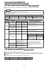
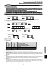
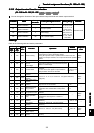
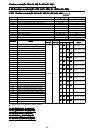
9
99
9(
((
(&
&&
&7
77
72
22
25
55
5
&
&&
&2
22
21
11
17
77
75
55
52
22
2/
//
/
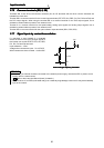
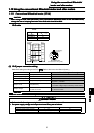
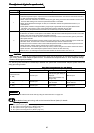
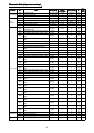
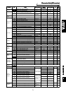
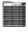
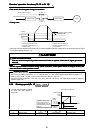
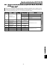
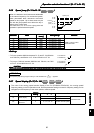
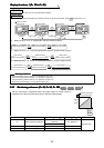
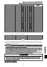
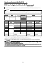
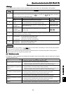
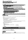
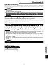
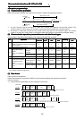
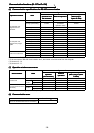
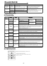
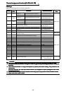
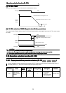
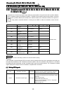
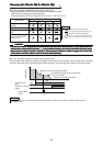
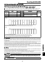
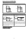
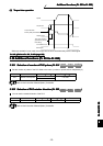
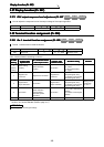
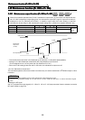
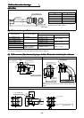
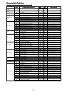
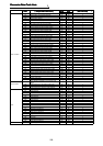
&RQGLWLRQDOSRVLWLRQFRQWURO3UWR3U3UWR3U
&RQGLWLRQDOSRVLWLRQFRQWURO3UWR3U3UWR3U&RQGLWLRQDOSRVLWLRQFRQWURO3UWR3U3UWR3U
&RQGLWLRQDOSRVLWLRQFRQWURO3UWR3U3UWR3U
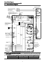
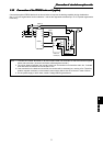
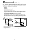
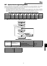
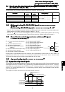
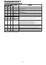
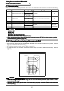
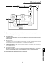
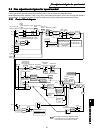
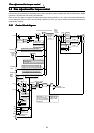
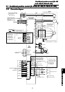
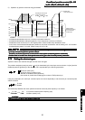
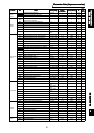
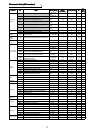
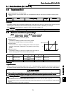
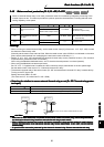
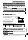
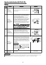
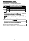
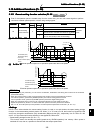
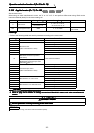
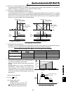
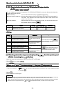
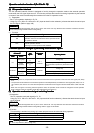
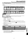
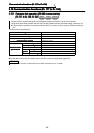
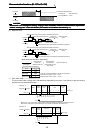
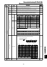
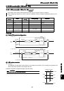
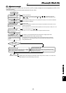
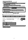
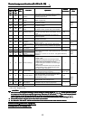
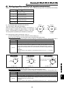
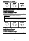
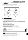
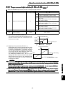
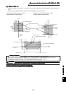
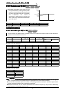
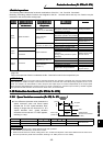
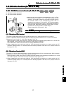
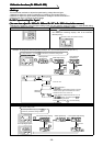
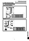
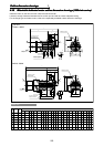
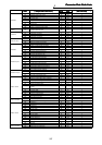
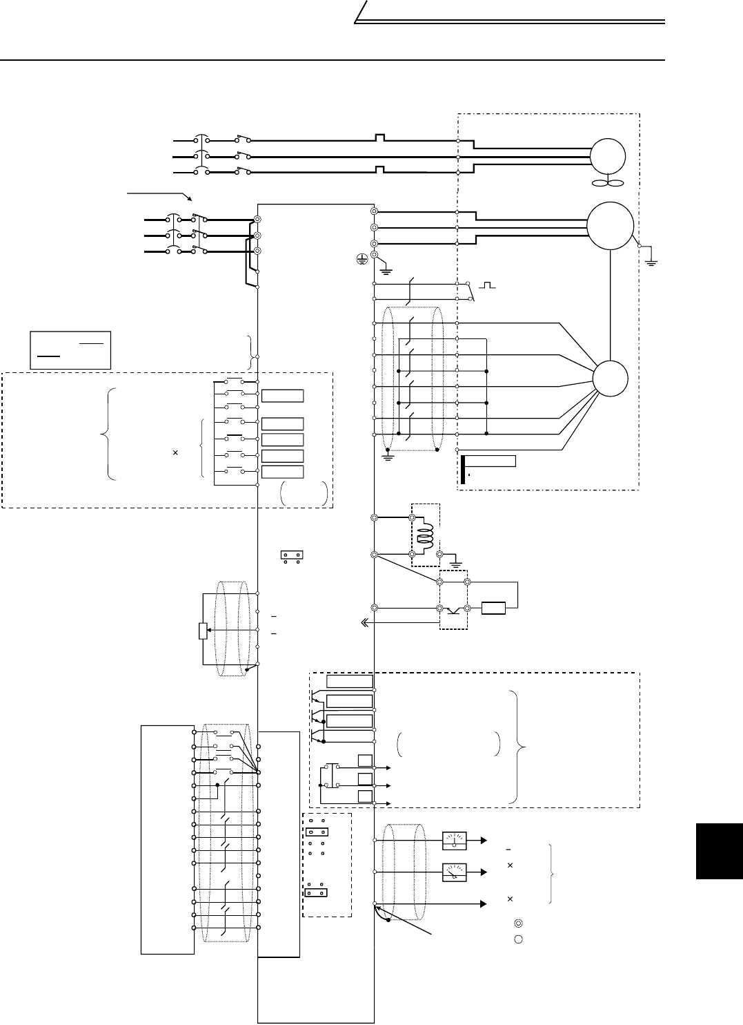
&RQQHFWLRQGLDJUDP
&RQQHFWLRQGLDJUDP&RQQHFWLRQGLDJUDP
&RQQHFWLRQGLDJUDP
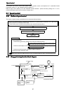
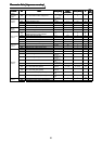
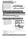
3-phase AC
power supply
Take care not to
short terminals
PC-SD.
Avoid frequent ON-OFF.
Repeated inrush currents at
power-on will shorten the
converter life.
(Switching life is 100,000)
NFB MC
External transistor common
24VDC power supply
Contact input common (source)
Terminals DI1 to
DI4 and STR vary
in function with
the input terminal
function selection
(Pr. 180 to Pr. 183,
Pr. 187) settings.
Forward rotation start
Reverse rotation start
Reset
Control input signals (no voltage input allowed)
Digital input
signal 4
STF
STR
RES
DI1(RL)
DI2(RM)
DI3(RH)
DI4(RT)
SD
Match phase sequence.
Contact
input
common
Earthing (Grounding)
(Open collector output)
Open collector output
common
Terminals DO1 to DO3
and ABC vary in function
with the output terminal
function selection
(Pr. 190 to Pr. 192,
Pr. 195) settings.
12 bits
12 bits
Analog signal output
(Analog output common)
Main circuit terminal
Control circuit terminal
Any of three different
signals can be selected
using the parameter.
10V
1ch
+
0 to 10V
1ch
R
S
T
R1
S1
PC
V
W
OH
SD
PA
PAR
PB
PBR
PZ
PZR
SE
DA1
DA2
5
U
V
W
U
PLG
IM
(-)
(+)
C
B
A
(RUN)
DO1
DO2
DO3
(SU)
(IPF)
5V
12V
24V
EXT
Differential
Complimen-
tary
Alarm output
(Contact output)
PG
SD
SINK
SOURCE
load impedance of 10k or more
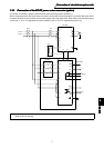
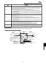
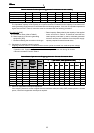
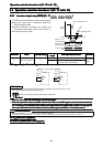
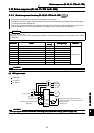
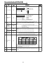
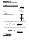
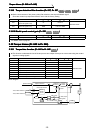
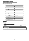
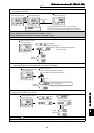
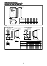
Vector inverter
(FR-V500L)
(+)
10E(+10V)
1( 10V)
3( 10V)
2
(0 to +10V)
(Positioning module)
QD75
MELSEC-Q
PGP
DGN
SD
VDD
RDY
VDD
OP
CR
SD
OPC
PP
PGP
NP
PGN
FLS
RLS
DOG
STOP
RDY COM
RDY
CLEAR
PULSE R
+
+
Torque restriction
command
5(Common)
(FR-V5AP)
PULSE F
COM
PGO 24
PGO COM
CLEAR COM
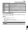
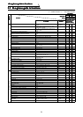
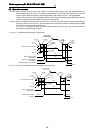
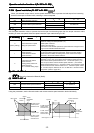
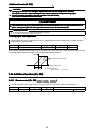
NFB MC
Match phase sequence.
(Fan should have intake rotation.)
R
S
T
FAN
OCR
A
B
C
The pin numbers each of motor are different.
A
B
C
D
G
S
R
F
N
Motor
Verify the power specification
of the motor cooling fan when
performing wiring.
Thermal
protector
When using the motor
not equipped with a
thermal protector,
set Pr. 9 and Pr. 876
= "0"
G1
G2
REMARKS
E
(-)(+)
Meter
P1
P1
N
CN8
P
PE
DCL(Standard)
Earthing
Brake resistor
(option)
Brake unit
(option)
PR
P
5HIHUWRSDJH