Chapter 2. Connecting 29
Connecting a DVD Player with Component Video
Connecting a DVI Device
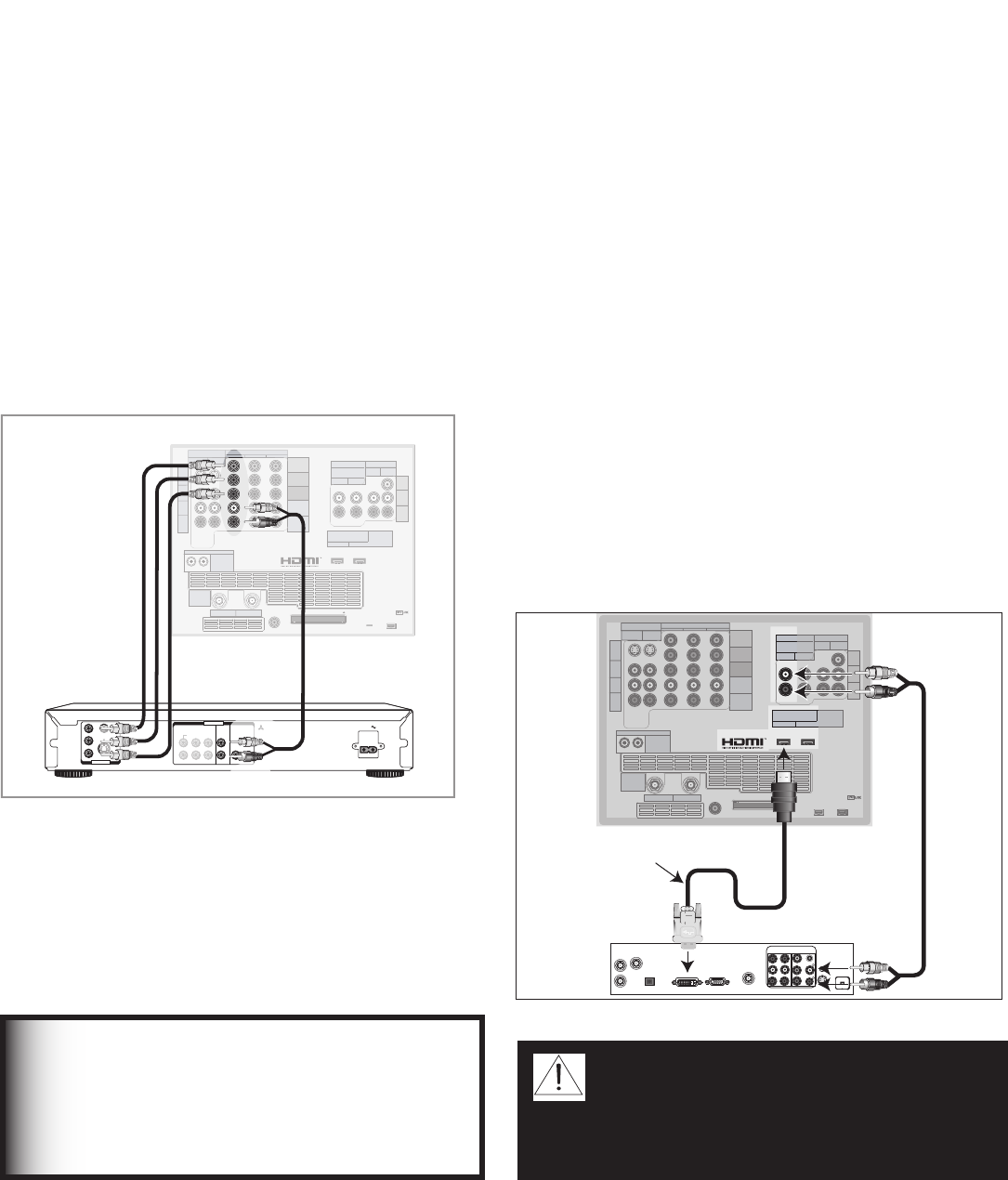
DVD Player with Component Video
Figure 9
Component video cables and audio cables are required.
These are not included with the TV.
1. Connect the Component Video cables from Y/Pr/
Pb VIDEO OUT on the back of the DVD player to
COMPONENT-2 on the TV back panel, matching the
correct connection:
• Y to Y (Green)
• Pr to Pr (Red)
• Pb to Pb (Blue)
2. Connect a set of audio cables from AUDIO OUT
on the back of the DVD player to COMPONENT-2
AUDIO Input on the TV back panel. The red cable
connects to the R (right) channel, and the white cable
connects to the L (left) channel.
COMPONENT
YPbPr (480i/480p/720p/1080i)
INPUT
1
2
S-VIDEO
VIDEO
AUDIO-
LEFT/
(MONO)
AUDIO-
RIGHT
DTV/CABLE/
VHF/UHF
ANT 1 / MAIN
ANT 2 / AUX
DIGITAL
AUDIO
OUTPUT
CableCARD™
USE WITH
ANT 1 CARD TOP
1
2
Y
Pb
Pr
AUDIO-
LEFT/
(MONO)
AUDIO-
RIGHT
OUTPUT
AUDIO
OUTPUT
RECORD
OUTPUT
DVI
Analog Audio
1 2
VIDEO
AUDIO-
LEFT/
(MONO)
AUDIO-
RIGHT
MONITORLINK™/HDMI
VIDEO 480i/480p/720p/1080i
AUDIO PCM LINEAR
1
2
IEEE 1394
INPUT/
OUTPUT
Net Command
IR EMITTER
¸
',INK
¸
INPUT
PC - 60Hz
VGA, W-VGA,
SVGA, W-SVGA,
XGA, 1280 X 720
57#BDL1BOFM4FDUJPO
7*%&0
4
:
$
#
$
3
7*%&0065
#*5453&".1$.$)463306/% $)
-
3
$&/5&3
46#800'&3463306/% '30/5 $0"9*"- 015*$"-
"6%*0065
"$*/
.*546#*4)*
%7%1-":&3
.0%&-
%%
108&34611-:7_)[
108&3$0/46.15*0/8
.*546#*4)*%*(*5"-&-&$530/*$4
%*453*#65&%#:
+&30/*.030"%
*37*/&$"
."%&*/+"1"/
".&3*$"*/$
4&3*"-/0
."/6'"$563&%
%7%#BDL1BOFM
3FE
8IJUF
8IJUF
3FE
Figure 9. Connecting a DVD Player with Component
Video
Note: NetCommand® assumes you connected your
DVD player to Component-2. If you add a second
DVD or use any other inputs for your DVD, this change
must match in the NetCommand system. See Edit
NetCommand... in Chapter 3 for more information.
IMPORTANT
See Appendix B for component video signal
compatibility information.
For digital audio connections to your A/V
receiver , see your DVD player and A/V
receiver Owner’s Guides.
DVI Device
Figure 10
A DVI-to-HDMI cable or DVI/HDMI adaptor and HDMI cable
and audio cables are required. These are not included with the
TV. They may be available at your local electronics retailer.
1. Connect the DVI-to-HDMI cable (recommended) or
HDMI cable with DVI/HDMI adaptor from the DVI
device’s back panel to the TV back panel.
NOTE: If you are using a DVI/HDMI adaptor, it is
important to connect the adaptor to the DVI device
for best performance.
2. Connect a set of audio cables from AUDIO OUT
on the DVI device back panel to the INPUT/DVI
Analog Audio on the TV back panel. The red cable
connects to the R (right) channel, and the white
cable connects to the L (left) channel.
NOTE: The HDMI connection supports copy
protection (HDCP). Some devices require
connecting to an analog input first, in order to view
on-screen menus and select DVI as the ouput.
Please review your equipment instructions for DVI
connectivity and compatibility.
!.4
#!",%
3!4%,,)4%
46/54
!5$)/
2
,
$6)/54
%7*%FWJDF
COMPONENT
YPbPr (480i/480p/720p/1080i)
INPUT
1
2
S-VIDEO
VIDEO
AUDIO-
LEFT/
(MONO)
AUDIO-
RIGHT
DTV/CABLE/
VHF/UHF
ANT 1 / MAIN
ANT 2 / AUX
DIGITAL
AUDIO
OUTPUT
CableCARD™ USE WITH ANT 1 CARD TOP
1
2
Y
Pb
Pr
AUDIO-
LEFT/
(MONO)
AUDIO-
RIGHT
OUTPUT
AUDIO
OUTPUT
RECORD
OUTPUT
DVI
Analog Audio
1 2
VIDEO
AUDIO-
LEFT/
(MONO)
AUDIO-
RIGHT
MONITORLINK™/HDMI
VIDEO 480i/480p/720p/1080i
AUDIO PCM LINEAR
1
2
IEEE 1394
INPUT/
OUTPUT
Net Command
IR EMITTER
¸
',INK
¸
INPUT
PC - 60Hz
VGA, W-VGA,
SVGA, W-SVGA,
XGA, 1280 X 720
%7*UP)%.*$BCMF
57#BDL
1BOFM%FUBJM
Figure 10. Connecting a DVI Device
CAUTION: To ensure continued FCC
compliance, the user must use a
shielded video interface or HDMI cable
with bonded ferrite cores at both ends
when using the PC input.
