


4.1. Controls
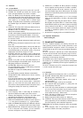
4.1.1. Front Panel
1a POWER: Switches the power to the receiver ON and OFF.
1b VOLUME: The VOLUME pot matches the receiver’s output
level to the input sensitivity of your mixer or amplifier.
1c TCSQ: The TSCSQ (Tone Code Squelch) automatic squelch
circuit mutes the receiver if the received signal is too weak or
the transmitter switched off, effectively suppressing the audible
noise caused by an excessive drop in received signal
strength. The squelch circuit is controlled by a pilot frequency in
the transmitter signal and there f o re needs no user- a d j u s t a b l e
control.
1d CHANNEL: This rotary switch selects the desired carrier fre-
quency or its alternative frequencies.
1e BATTERY HI, MID, LO: These three LEDs indicate the current
status of the transmitter batteries:
HI, MID, and LO lighting constantly indicate the batteries will last
for more than 6 hours (re c h a rgeable batteries: 5 hours max.).
MID and LO lighting constantly indicate the batteries will last
for more than 3 hours.
LO (red) lighting constantly indicates the batteries will last for
1 hour.
LO (red) blinking indicates the batteries will be down in less
than 1 hour.
When using rechargeable batteries, note that only MID and
LO may light even if the batteries are fully charged. This
means that depending on the capacity, quality, or age of the
batteries their maximum life is approx. 4 hours.
1f MUTE LED: Lights red if the squelch is active. In this case the
audio output will be muted. Note that the MUTE LED does
not indicate the position of the MUTE switch on the trans-
mitter!
1g RF LEDs: One yellow and four green LEDs indicate the re-
ceived field strength of the transmitter signal. Only the yellow
LED lighting indicates low field strength.
1h AF/PEAK LEDs: Indicate the received audio level.
The green LEDs lighting and the red LED flashing occasional-
ly indicate optimum modulation.
If the LEDs do not light, the sensitivity setting on the transmitter
is too low.
The red LED lighting constantly indicates overmodulation.
1i Diversity LEDs A and B: Indicate which of the two receiving
antennas is active.
If you use remote antennas, only one LED lighting constantly
indicates that the cable to the other antenna has broken.
1j Color Code: If you use the receiver within a multichannel
system, you may remove the black plastic platelet and re-
place it with a colored platelet included in the optional Color
Coding Kit to identify each channel by a different color.
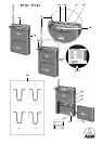
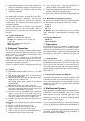
4.1.2. Rear Panel
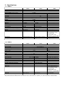
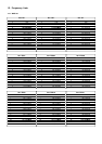
1k Carrier Frequency Table: A label listing the available fre-
quencies is affixed to the bottom panel of the receiver.
1l Frequency Set Designation: The label on the bottom panel
also indicates the designation of the Frequency Set.
1m POWER: Input connector for the supplied AC adapter.
1n AUDIO OUT UNBALANCED: Unbalanced audio output on a
1/4” mono jack for connecting to, e.g., a guitar amplifier.
1 o AUDIO OUT BALANCED: Balanced 3-pin XLR audio output for
connecting to, e.g., a microphone input on the mixing console.
1p BALANCED LINE/MIC: Switches the balanced audio output
to line or microphone level. Therefore, you can connect the
receiver to microphone or line level inputs as desired.
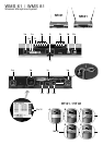
1q ANTENNA A, ANTENNA B: BNC sockets for connecting
the two supplied receiving antennas. The SR 61 and SR 81
are diversity receivers and use two antennas in order to re-
ceive the transmitter signal at two different spots. The diversity
electronics will automatically activate the antenna that delivers
the better signal.
Each ANTENNA socket provides a 4.2 V/35 mA supply
voltage for the optional RA 61 B or RA 81 B remote booster
antennas.
In a multichannel setup using the optional PS 61 or PS 81
Power Splitter and optional PSU 01 Central Power Supply,
the ANTENNA sockets are also used as inputs for the supply
voltage delivered by the PSU 01. In this configuration, be
sure not to use the supplied external AC adapter. For details
on setting up multichannel systems, refer to the PS 81 or
PS 81 Manual.
1r Screwdriver for adjusting GAIN and CHANNEL controls.
4.2. Optional Accessories
Color Coding Kit
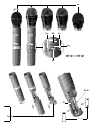
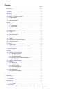
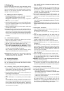
5. Handheld Transmitter
The HT 61 handheld transmitter and matching microphone ele-
ments (optional) provide the same acoustic performance as the
equivalent hardwire microphone versions. The microphone ele-
ments available for the HT 61 have been specifically designed for
vocal use.
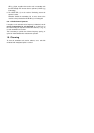
The HT 61 operates in a subband up to 4 MHz wide within the
138 MHz to 250 MHz VHF carrier frequency range. The HT 61
can be switched to a maximum of 15 different carrier frequencies
depending on local frequency allocations.
The transmitter uses a dipole antenna integrated in the body.
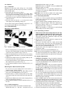
The controls can be protected against accidental misadjustment
collectively (2d) or individually with the supplied adjustable pro-
tective ring (2j).
The HT 81 is identical to the HT 61 except that it operates in the
710 MHz to 869 MHz UHF range
5.1. Controls
2a PWR: Switches the transmitter power ON (“I”) and OFF (“0”).
2b Status LED: Indicates battery status and audio input overload.
LED glowing dimly: batteries are OK.
LED constantly lighting brightly: batteries will be dead in
about 60 minutes.
LED illuminating brightly: audio input is overloaded.
2c MIC: Mutes the audio signal (position “0”) while power and
carrier frequency remain ON.
2d Color Code: If you use the transmitter in a multichannel system
you can remove the black plastic ring and replace it with a
colored ring from the optional Color Coding kit to identify
each wireless channel by a different color.
2e GAIN: This rotary pot allows you to match the microphone
level to the transmitter’s audio section.
2f Battery Compartment: Refer to Section 9. Setting Up.
2g CHANNEL: This rotary switch selects the desired carrier fre-
quency (depending on local allocations) or switches between
the carrier frequency and its alternative frequencies.
Important: Prior to selecting frequencies, switch the transmitter
OFF.
2h Carrier Frequency Table: A label listing the available fre-
quencies is affixed to the battery compartment.