


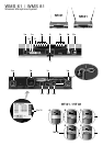


9. Setting Up
Prior to connecting the receiver to AC power and inserting the bat-
teries into the transmitter, set the transmitter and receiver to the
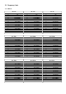
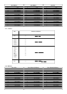
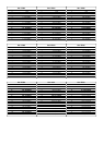
same carrier frequency. The carrier frequency tables on the trans-
mitter (2h, 3k) and receiver (1k) list the channel number corre-
sponding to each carrier frequency.
9.1. Selecting the Carrier Frequency
1. Handheld transmitter: Unscrew the battery compartment
cover and the color code ring (2d or 2j) CCW.
Bodypack transmitter: Open the battery compartment
(3h).
All controls are now accessible.
2. Use the supplied screwdriver (1r) to set the CHANNEL control
(2g) on the handheld transmitter or (3f) on the bodypack trans-
mitter to the desired channel.
3. Set the CHANNEL control (1d) on the receiver to the same
channel as the transmitter.
Important: Be sure to switch power to the transmitter OFF every
time before changing the carrier frequency. The new carrier fre-
quency will not be activated before you switch the transmitter
back ON. (If you change the carrier frequency while the trans-
mitter is ON, the transmitter will remain tuned to the old carrier
frequency.)
9.1.1. Multichannel Systems
1. Be sure to assign a separate carrier frequency to each trans-
mission channel (transmitter + receiver).
2. Set the transmitter and receiver to one of the frequencies mark-
ed with * in the carrier frequency tables (1k, 2h, 3k).
Note: If reception on the selected carrier frequency is disturbed,
set the carrier frequencies for all channels up or down
one or two notches using the respective CHANNEL controls
(1d, 2g, 3f) on each transmitter and receiver.
This is necessary to provide the minimum frequency spacing
required for intermodulation-free multichannel operation.
Important: Do not operate two or more channels on the same
frequency at the same time and location. This would cause
unwanted noise due to radio interference.
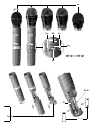
9.2. Handheld Transmitter
9.2.1. Microphone Element
Prior to switching the transmitter on, screw the microphone element
CW onto the thread on the transmitter. All electrical connections
will be made automatically.
9.2.2. Inserting, Testing, and Removing Batteries
1. Make sure that the end of the ribbon fixed inside the battery
compartment (2f) will stick out of the battery compartment (2f).
(The ribbon is needed for removing the batteries.)
2. Insert the supplied batteries into the battery compartment (2f)
conforming to the polarity marks.
The transmitter will not function with incorrectly inserted batte-
ries.
3. Set the PWR switch to “I” to switch the power to the transmitter
on.
The status LED (2b) will flash momentarily. If the batteries are in
good condition, the status LED (2b) will continue glowing dimly.
When the status LED (2b) illuminates brightly the batteries will
be dead within about 90 minutes. Replace the batteries with
new ones as soon as possible.
If the status LED (2b) fails to illuminate the batteries are dead.
Insert new batteries.
4. Screw the supplied protective ring (2j) and the battery com-
partment cover back onto the transmitter CW. You can rotate
the protective ring (2j) so that any one of the controls will be
accessible and all others covered (B to E) and thus protected
from being misadjusted unintentionally.
Note: For easy channel identification in a multichannel setup, you
can install a different-color protective ring included in the
optional Color Coding Kit. These protective rings are adjust-
able, too.
Note: If you prefer to cover all controls, reinstall the original color
code ring (2d) after adjusting the system as described
in section 9.6.
5. Removing batteries: Pull the ribbon outward to release the
batteries from the battery compartment (2f) and remove the bat-
teries.
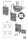
9.3. Bodypack Transmitter
1. Insert the supplied batteries into the battery compartment (3h)
conforming to the polarity marks.
The transmitter will not function with incorrectly inserted bat-
teries.
2. Close the battery compartment (3h). The GAIN control (3j)
remains accessible through an opening in the battery compart-
ment cover.
3. Connect your microphone -- or your instrument using an option-
al MKG/L guitar cable -- to the audio input (3d).
4. Rotate the security cover (3m) CW to uncover the switches.
5. Set the POWER switch (3a) to “I” to switch the power to the
transmitter on.
The status LED (3c) will flash momentarily. If the batteries are in
good condition, the status LED (3c) will continue glowing dimly.
When the status LED (3c) illuminates brightly the batteries will
be dead within about 90 minutes. Replace the batteries with
new ones as soon as possible.
If the status LED (3c) fails to illuminate the batteries are dead.
Insert new batteries.
6. Snap the security cover (3m) back over the switches CCW.
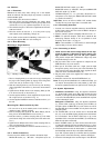
You can wear the transmitter inside a shirt or jacket pocket, fix
it to your belt with the belt clip (3g), or attach it to your body
with adhesive bandage.
Important: Make sure the antenna will hang down freely, with-
out being covered by the body.
Note: For easy channel identification in a multichannel setup, you
can replace the snap fitted color code platelet (3e) with a dif-
ferent-color platelet included in the optional Color Coding Kit.
9.4. Replacing Transmitter Batteries
In order to ensure proper functioning of the BATTERY status display
on the receiver, make sure to
- use 2 new batteries of the same type and make only;
- check that the batteries were not used for at least two hours
prior to inserting them; and
- do not remove batteries before they are dead (the BATTERY
LO LED on the receiver will flash).
If you use rechargeable batteries, be sure to use only high qua-
lity branded batteries, e.g., from SANYO. Note that the
discharge curve of any rechargeable battery will change over
time. Therefore, the BATTERY display on the receiver may oper-
ate less accurately with older rechargeable batteries.