


Operating Determinations
When installing this mixer, please make sure that the device is not exposed to extreme heat, moisture or dust! There
should not be any cables lying around. Doing so endangers you as well as others. Do not operate the mixer in extremely
hot (more than 30° / 100°F) or extremely cold (less than 5°C / 40°F) surroundings. Keep away from direct sunlight and
heaters.
Operate the mixer only after becoming familiar with its functions. Do not permit operation by persons not qualified for
operating the mixer. Most damages are the result of unprofessional operation!
Never use spray cleaners to clean the faders! Never use solvents or abrasive detergents to clean the mixer! It is recom-
mended that you use a soft damp cloth. Please consider that unauthorized modifications on the device are forbidden
due to safety reasons!
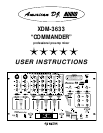
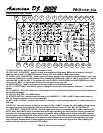
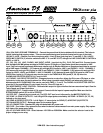
Connections (Refer to diagrams on pages 5 & 6)
• Make sure that the POWER SWITCH (1) is set to OFF. Before connecting other devices to the mixer, all units have to
be switched off and the MASTER FADER (31) is set to min.
• Make sure that the available voltage is not higher than stated on the voltage selector (50) before connecting to power.
• In order to obtain the highest sound quality, only use high quality American DJ®, Ameri-Cable ™ cables for connecting
devices. Make sure that the cables are properly fixed.
• Connect your amplifier to the MASTER OUTPUT jacks (43) or BALANCED OUTPUT XLR jacks (47). Make sure that
(L & R) channels are set properly. For mono or bridged operation, you should use the the BALANCED OUTPUT XLR
jacks (47) and set the MASTER MONO/STEREO switch (32) to MONO.
• For recording, connect your tape recorder or cassette deck to the REC OUT jacks (44). The REC OUT level will not be
influenced by the MASTER FADER (31).
• The XDM-3633 features three microphone inputs. MIC 1 and MIC 2 Neutrik™ connector jacks (9) are on the front
panel for 1/4 inch (6.3mm) jack plugs or XLR-plugs. With the TALKOVER switch associated with MIC 1 (11), you can
attenuate all other signals without affecting the microphone volume. You can switch MIC 1 and MIC 2 (11) off by setting
the TALKOVER SWITCH to MICRO OFF. The 1/4 inch (6.3mm) MIC 3 jack (36) is on the rear panel. You can connect
your third microphone here. Adjust the microphone volume for MIC 3 by using the channel fader for CHANNEL 4. Make
sure that the LINE 5/LINE 6/ MIC 3 SWITCH is set to MIC 3. CAUTION: You can only cut the MIC 3 jack (36) off by set-
ting the CHANNEL 4 fader to 0 or by switching the LINE5/LINE6/MIC 3 SWITCH to LINE 5 or LINE 6.
• You can connect 3 turntables using the PHONO 1/AUX 1 (37), PHONO 2/AUX 2 (38), and PHONO3/AUX 3 (39) jacks
on the rear panel. You can only control the turntables signal after you have switched the PHONO /AUX SELECTOR
SWITCH (41) on the rear panel to PHONO, plus you must change the PHONO/AUX/LINE SWITCH (3) on the front
panel to PHONO/AUX. The signal is then controlled via the CH-1, CH-2, OR CH-3 faders (17).
• Connect your tape player, tuner, sound effects, CD player, and cassette decks etc. to the LEFT & RIGHT RCA LINE
signals (37, 38, 39, 40 & 41) on the rear panel. The signal is then controlled via the CH-1, CH-2 AND CH-3 faders (17)
when the PHONO/AUX SWITCH on the front panel (3) is switched to LINE . CD players, cassette decks etc. may also
be connected to the LEFT & RIGHT RCA PHONO/AUX jacks (37, 38 & 39) on the rear of the unit. You can only control
this signal after you have switched the PHONO / AUX SELECTOR SWITCH (41) on the rear panel to AUX, plus you
must change the PHONO/AUX/LINE SWITCH (3) on the front panel to PHONO/AUX. The signal is then controlled via
the CH-1, CH-2, CH-3, and CH-4 faders (17).
XDM-3633 User Instructions page 4