


©American DJ® - www.americandj.com - Flight Moon™ Instruction Manual Page 6©American DJ® - www.americandj.com - Flight Moon™ Instruction Manual Page 5
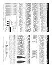
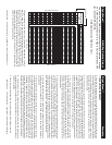
Flight Moon™ Controls and Functions
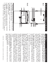
REAR
FRONT
1 2 3 4 5 6 7 8 9 10
ON
FUSE
2
8
5
4
3
1
6
7
11
12
10
9
1. Thumb Holders - These two thumb screw holders are designed to
secure the front panel when the unit is in use.
2. XLR Input Jack - This jack is used to accept an incoming DMX
signal or Master/Slave signal.
3. Microphone - This microphone receives external low frequencies
to trigger the unit in Sound-Active and Master/Slave mode.
4. Power Inlet/Fuse Holder - This housing stores a 5 amp GMA pro-
Flight Moon™ Controls and Functions
tective fuse and is also used as the main power supply connection. Use
only properly grounded IEC power cord. Always replace with the exact
same type fuse, unless other wise instructed, by an authorized Ameri-
can DJ
® service technician.
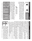
5. XLR Output Jack - This jack is used to transmit the incoming
DMX signal to another DMX fi xture, or transmit a Master/Slave signal
to the nest Flight Moon™ in the chain. For best results in DMX or
Master/Slave mode terminate this jack if it is the last unit in the
chain. See “Terminator” on page 12.
6. Flight Moon/C Controller Jack - This jack is for use with the
optional FlightMoon/C footswitch controller only. Do not attempt to con-
nect an audio signal this jack, this will damage the PC board and void
your manufactures warranty!
7 . Power Indicator - This light is used to indicate proper operation.
8. Dip Switches - These switches serve two functions. In master
slave mode these switches are used to assign a specifi c head
address. In DMX mode these switches are used to assign a DMX
address to the unit. In DMX mode each switch corresponds to a
specifi c value based on DMX encoding. See page 10 for a detailed
explanation of DMX encoding.
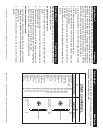
9. Mirror - This is a highly refl ective surface mirror specifi cally designed
to optimize and enhance beam output. Never use glass cleaner that
contains ammonia to clean the surface of the mirror (such as Windex).
10. Audio Sensitivity Knob - This adjust audio sensitivity of the
internal microphone (3). Turning the sensitivity knob in the clockwise
direction will increase the sensitivity to sound. Turning the knob in
the counter clockwise direction will decrease the fi xture’s sensitivity
to sound.
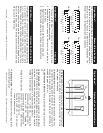
11. Lamp Socket Assembly Plate - This plate accesses the lamp
socket assembly. Lamp Socket Assembly - This assembly holds a
ZB-JCR H5 15v/150w lamp.
12. Focusing Adjustments - This thumb screws are used to focus the
high quality lens.