


©American DJ® - www.americandj.com - Flight Moon™ Instruction Manual Page 11 ©American DJ® - www.americandj.com - Flight Moon™ Instruction Manual Page 12
Flight Moon™ Set Up
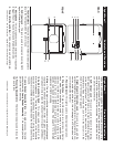
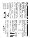
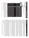
Figure 3
1 Ground
1 Ground
XLR Male Socket
XLR Pin Confi guration
3 Hot
2 Cold
2 Cold
3 Hot
XLR Female Socket
Pin 3 = Data True (positive)
Pin 2 = Data Compliment (negative)
Pin 1 = Ground
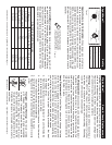
Special Note: Line Termination.
When longer runs of cable are
used, you may need to use a terminator on the last unit to avoid erratic
behavior. A terminator is a 90-120 ohm 1/4 watt resistor which is con-
nected between pins 2 and 3 of a male XLR connector (DATA + and
DATA -). This unit is inserted in the female XLR connector of the last
unit in your daisy chain to terminate the line. Using a cable terminator
(ADJ part number Z-DMX/T) will decrease the possibilities of erratic
behavior.
1
2
3
Termination reduces signal errors and
avoids signal transmission problems
and interference. It is always advisable
to connect a DMX terminal, (Resistance
120 Ohm 1/4 W) between PIN 2 (DMX-)
and PIN 3 (DMX +) of the last fixture.
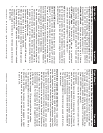
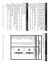
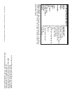
Figure 4
5-Pin XLR DMX Connectors.
Some manufactures use 5-pin XLR
connectors for DATA transmission in place of 3-pin. 5-pin XLR fi xtures
may be implemented in a 3-pin XLR DMX line. When inserting standard
5-pin XLR connectors in to a 3-pin line a cable adaptor must be used,
these adaptors are readily available at most electric stores. The chart
below details a proper cable conversion.
Conductor 5-Pin XLR Male (In)3-Pin XLR Female (Out)
Pin 1
Do Not Use
Do Not Use
Pin 3
Pin 2
Pin 1
Pin 3
Pin 2
Not Used
Not Used
Data True (+ signal)
Data Compliment (- signal)
Ground/Shield
3-Pin XLR to 5-Pin XLR Conversion
Flight Moon™ Fuse & Lamp Replacement
Caution: Always replace with the exact same type lamp and fuse,
unless otherwise specified by an authorized American DJ® technician.
Replace with anything other than the specified part can damage your
unit and will void your manufactures warranty.
Warning: If, after replacing the lamp or fuse either one continues
to blow, STOP using the unit. Contact customer support for further
instructions, you may have to return the unit for servicing. Continuing
to use the unit may cause serious damage.
Fuse Replacement: Disconnect the unit’s main power supply. Insert
a standard flat head screw driver in to the fuse holder housing. Turn
the screwdriver in counter-clockwise direction to remove the fuse
holder. Remove the fuse holder to expose the fuse. Remove the old
fuse and discard it. Replace the fuse with the same type. Insert the
fuse holder back into it’s housing and turn it in clockwise direction to
lock the holder in place.
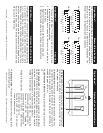
Lamp Replacement: Caution! Never attempt to change the lamp
while the fixture is plugged in. Always disconnect the main power and
allow the unit ample time to cool before attempting to replace the
lamp. Lamp replacement has been made simple by incorporating the
use of a flip-up front cover that is retained by thumb screws.
1. Be sure to follow the proper handling procedures that deal
with halogen lamps.
2. Remove the thumb screw on the top/rear of the unit that holds the
lamp socket assembly cover in place.
3. After removing the thumb screw, slide out the cove from the rear of
the unit to expose the lamp socket assembly.
4. Carefully remove the old lamp and discard it in the trash.
5. Replace the lamp with an exact match and reassemble in reverse
order.
Halogen Lamp Warning: This fixture is fitted
with halogen lamps which are highly susceptible
to damage if improperly handled. Never touch the
lamps with your bare fingers as the oil from your
hands will shorten lamp life. Also, never move the
fixture until the lamps have had ample time to cool.
Remember, lamps are not covered under warranty
conditions.