


7. ULTRA-MEDIANOS: Este es el control primor-
dial para el rango de las frecuencias medianas. Gire
el control del centro hacia la izquierda para lograr
un sonido de contorno (más distante, menor salida
en el rango mediano) ó del centro hacia la derecha
para obtener un sonido realmente penetrante.
8. AGUDOS: Esta perilla sirve como el control pri-
mordial para las frecuencias altas. Esto permite un
rango de 17 dB de refuerzo ó 22dB de recorte a
5kHz.
9. EQ EN LED: Este LED indicador se ilumina
cuando usted activa el EQ mediante el control
Maestro (#11) del panel delantero ó el interruptor de
pie (#23) del panel posterior.
10. EQ GRAFICO: Estos controles deslizantes
(cursores) le permiten ajustar la salida de las fre-
cuencias que se muestran junto a cada control. La
posición central de cada control es plana (sin
refuerzo ni recorte). Estos controles sólo afectan el
sonido cuando el EQ esé prendido.
11. MAESTRO: Fije mediante este control el nivel
general de salida del amplificador. El Circuito de
Efectos y la Salida Equilibrada (#18, 19, 22) no se
verán afectadas por el control Maestro. Jalando el
control Maestro se prende el EQ Gráfico (#10).
Cuando se utiliza el interruptor de pie, se pasa por
alto el interruptor del panel delantero.
12. DIODO LED DE LIMITE: Este LED indicador
parpadeará cada vez que se requiera el circuito lim-
itador interno para conservar limpia la señal de sal-
ida del amplificador. Esto indica que el amplificador
está aproximándose a su salida máxima y que el
limitador está impidiendo el aplanamiento (“clip-
ping”) de la señal de salida.
13. DIODO LED DE POTENCIA ENCENDIDA:
Este LED indicador se ilumina cuando se prende el
interruptor de POTENCIA (#14).
14. INTERRUPTOR DE POTENCIA: Este interrup-
tor de servicio pesado tipo vaivén aplica la energía
de CA al amplificador: el amplificador se PRENDE
en la posición hacia arriba, y se APAGA en la posi-
ción hacia abajo
SVT-150H
4
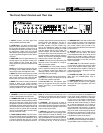
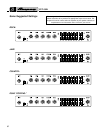
The Front Panel Controls and Their Use
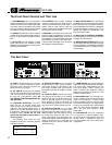
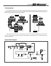
The Rear Panel
1615 17 18 19 20
21
22 23
Made in the U.S.A. by SLM ELECTRONICS
1400 Ferguson Avenue • St. Louis, MO 63133
15. FUSE: This protects the unit from dam-
age due to overload conditions or power
line surges. If the fuse blows, replace it only
with the same size and type.
16. AC LINE IN: Firmly plug the supplied
AC power cord into this socket, pushing it in
until it is fully seated. Plug the male end of
the cord into a grounded AC outlet. DO
NOT DEFEAT THE GROUND PRONG OF
THE AC PLUG!
17. SPEAKER OUTPUT(S): The SVT-
150H has two 1/4” speaker output jacks
which you will use to connect to your bass
cabinet(s). Use speaker cables with 1/4”
plugs to connect the SPEAKER jack(s) to
the cabinet(s). Observe the 4 ohm minimum
impedance rating. Please see the note
concerning the speaker output jacks on
the facing page.
The following chart shows the total
impedance load when connecting speaker
cabinets in parallel:
Cabinet # of Total
Impedance Cabs Impedance
8Ω 24Ω
16Ω 28Ω
16Ω 44Ω
18. EFFECTS RETURN: To use an external
effects device or other signal processor,
connect the OUTPUT of the device to this
jack using a shielded cable. This feeds the
processed signal into the amplifier’s master
section.
19. EFFECTS SEND: Connect the output
from this jack to the INPUT of an external
effects device using a shielded cable. This
sends a post-EQ signal to your effects.
Since plugging a cable in here does not
break the through connection to the power
amp, this can be used as another line out.
20. PRE/POST SWITCH: You can select
either pre or post-EQ for the signal at the
Balanced Out jack (#22) with this switch.
With the switch in the OUT position, the sig-
nal at the jacks will be pre-EQ. This is a
direct output which is not affected by any
EQ or boost settings. With the switch in, the
signal is post-EQ and is controlled and
modified by the tone controls, Graphic EQ
and Effects Loop.
21. -20dB SWITCH: This switch adjusts the
output level at the Balanced Out jack (#22).
The switch works independently from the
front panel Master control. Pushing the
switch in activates the -20dB pad, allowing
patching into microphone inputs on a mixer
without overdriving them.
22. BALANCED OUT: This XLR-type con-
nection supplies a balanced preamp output
signal for connecting to a house mixing
board, recording console or external ampli-
fiers with balanced inputs. The signal can be
set to pre or post-EQ by the Pre/Post switch
(#20). The level can be adjusted for either
mic or line type inputs using the -20dB
switch (#21).
23. FOOTSWITCH: This jack accepts the
1/4” plug from a 1-button footswitch, allow-
ing remote control of the Graphic EQ on/off
function. When a footswitch is used, the
front panel Master Pull EQ On switch (#11)
is bypassed.