


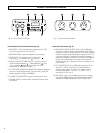
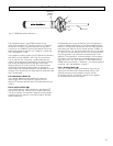

Front Panel Controls and Functions (Fig. B)
1. MONITOR:
1
/4" (6.3 mm) Monitor headphone jack; TRS
type with signal on both Tip and Ring.
2. MONITOR LEVEL: Monitor headphone level control.
3. FILTER SWITCH: 3-position switch offers Flat ( ) ,
High-pass ( ) and Band-pass ( ) settings.
4. MODE (PICKUP PATTERN) SWITCH: 3-position switch
offers Full-field Adaptive ( ) , Planar-adaptive ( ) and
Line + Gradient ( ) settings. (See page 5 for a full
explanation of the Mode settings.)
5. LCD BATTERY CONDITION INDICATOR: Markers disappear
as power remaining decreases. Functions only during 9V
battery operation using the AT895BH.
6. POWER LED INDICATOR: Lights red when power is on.
7. POWER SWITCH: On/off switch controls DC power from
all sources.
4
AT895CP Controls and Functions
Rear Panel Functions (Fig. C)
8. BALANCED AUDIO OUTPUT JACK: 3-pin XLRM-type
connector. Output is analog; the balanced signal appears
across Pins 2 and 3. Output phase is “Pin 2 hot;” positive
acoustic pressure produces positive voltage at Pin 2. Pin
1 is ground (shield). A standard 2-conductor shielded
cable (not included) can be used to connect the AT895CP
output to the associated electronics. Phantom power
cannot be used, but if present will have no effect on the
Control Pack.
9. DC POWER INPUT: 4-pin XLRM-type connector for an
external 12-14V DC source from an Anton/Bauer or
similar battery supply, or from an AC adapter. Wiring
is industry-standard: V– on Pin 1, V+ on Pin 4, no
connection to Pins 2 or 3.
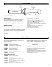
10. MIC INPUT JACK: 7-pin XLRM-type connector accepts
the special AT895C 6-conductor shielded cable used to
connect the AT895 Microphone to the Control Pack.
Fig. B Control Pack Front Panel
Fig. C Control Pack Rear Panel
1
2
7
8
9
10
3
5
6
4