


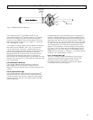

The microphone array in the AT895 consists of one
Audio-Technica MicroLine
®
element and four A-T cardioid
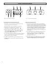
elements mounted in a co-planar diamond configuration.
A switch on the AT895CP Control Pack selects from three
Mode (pickup pattern) options: two “adaptive” modes and
one “non-adaptive” mode.
In the adaptive modes, signals from the MicroLine
®
element
and either one pair (labeled 1 & 2 in Fig. D) or both pairs
(1 & 2, 3 & 4) of the “corrective” cardioid elements are
utilized. These signals are processed in the Control Pack by
both analog and digital means to provide continuously-
adapting rejection of off-axis sounds. This means that as
the off-axis soundscape changes (either in intensity or
directionality) the microphone system compensates for those
changes. Even off-axis wind is interpreted as unwanted noise,
and is suppressed.
Full-field adaptive Mode ( )
The Full-field adaptive mode provides the maximum
directionality and off-axis rejection. Signals from the
MicroLine
®
element and both pairs of cardioid elements are
utilized.
Planar-adaptive Mode ( )
In the Planar-adaptive mode, signals from the MicroLine
®
element and only the “vertical” pair of cardioid elements
(1 & 2) are utilized. The resultant “elliptical” pickup pattern
provides optimum rejection in one plane (tighter vertically,
wider horizontally).
Mode (Pickup Pattern) Settings
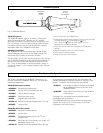
Understanding the correct orientation of the microphone is
crucial for effective application of the Planar-adaptive mode.
When the microphone is positioned with the Audio-Technica
logos along the
sides
of the mic handle and the “AT895” on
the name ring is “up” (as shown above and in Fig. A on page
3), maximum off-axis rejection occurs in the vertical plane of
the pickup pattern only, while the horizontal pickup is non-
adaptive. This produces a “horizontal ellipse” pickup pattern.
(Of course, if the microphone is rotated 90 degrees, so the
logos are at the “top” and “bottom” of the handle and the
AT895 name ring marking is “sideways,” the resulting pattern
would be “tall” and adaptively “narrow.”)
Line + Gradient Mode ( )
The Line + Gradient mode is non-adaptive, with only the
signal from the MicroLine
®
element being utilized. (The
cardioid elements and the adaptive circuitry are still
functioning, but the “correcting” signals are not applied
to the MicroLine
®
element’s signal.)
5
Fig. D AT895 Microphone Elements
Model No.
“AT895”
at “Top”
MicroLine
®
1
4
3
2