


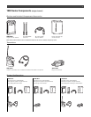
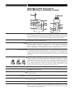


Output
Receiver Level Control
Monitor Level Control
DC Input
Monitor Output
(rear panel)
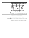
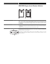
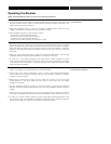
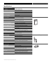
Balanced Audio Output Jack: TA3M-type connector. Pin 1: ground (shield); Pin 2: “audio +”;
Pin 3: “audio –”. A standard 2-conductor shielded cable can be used to connect the receiver
output to a balanced microphone-level input on a camera, mixer or integrated amplifier.
Controls the output level of the receiver.Turn clockwise to increase output level.
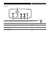
The level control (volume control) for headphones is independent of other level controls.Turn to
the right to increase output (turn up the volume).
You may connect the unit to an external power supply (12V DC source, 500 mA nominal
current, not included.)
3.5 mmTRS headphone jack.
7
1110
8
7
8
9
10
11
7
9
7
PIN 1 PIN 3
P
IN 2