


Receiver Setup
Location
The ATW-R100(x) receiver is designed primarily to be
mounted to professional video cameras using the included
hook & loop fasteners (mounting methods and positions will
vary with the camera being used). However, the receiver
will provide outstanding professional performance in other
wireless applications as well.
For best operation the receiver should be at least three feet
above the ground and at least three feet away from a wall or
metal surface to minimize reflections. The transmitter should
be at least three feet from the receiver.
Keep antennas away from noise sources such as computers,
motors, automobiles and neon lights; also keep antennas
away from large metal objects.
Output Connections
There is one balanced audio output (31.6 mV) on the back
panel of the receiver. Use shielded audio cable to connect this
XLRM-type 3-pin jack to the mic audio input of the camera or
mixer. (The optional AT8341 cable, 19" long, terminates in a
right-angle 3.5 mm stereo mini-plug.)
A headphone jack and level control permit monitoring of
the audio signal. Either mono or stereo headphones with
a 3.5 mm plug may be used; the audio is supplied to both
sides of a stereo unit.
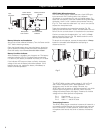
Antennas
Attach the antennas to the antenna input jacks. Make certain
that during operation there is a clear open-air path between
the receiver antennas and the transmitter.
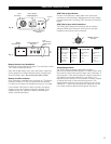
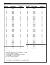
Power
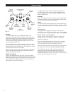
The ATW-R100(x) receiver operates on either external DC or
internal battery power by setting the Power switch to “EXT”
or “INT” respectively (Fig. A). In the center position all power
is off.
External Power
The back panel is equipped with a jack for an external
12-18V DC source, 200 mA nominal current. The jack takes a
standard 2.5 mm I.D. coaxial DC power plug, center
positive
.
Battery Selection and Installation
Always use two fresh alkaline 9V batteries. Replace the
batteries in pairs. Turn the Power switch “Off” before
inserting the batteries.
Open the hinged battery door on the side of the receiver.
Insert two batteries, observing correct polarity as marked
on the inside of the door. Close and latch the door.
Note that the battery door will not close fully if the batteries
are installed incorrectly.
Do not force the door closed.
The U100 Series receiver and transmitters accept most
popular brands of 9-volt alkaline batteries. But there is
considerable variation in battery sizes; some alkaline and
extended-life batteries may not fit correctly, which can cause
units to operate improperly or not at all.
4
BA
PWR
PEAK
X
10
ANT.A ANT.BMONITOR
MONITOR
LEVEL INT OFF EXT
OUT
LEVEL
X
1
0
5
4
3
2
1
9
8
7
6
0
5
4
3
2
1
9
8
7
6
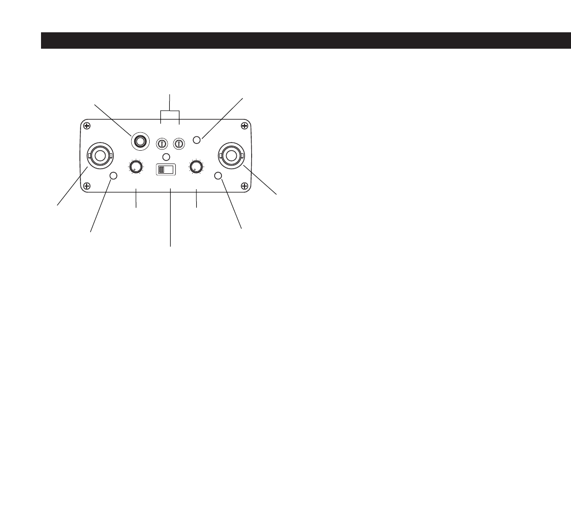
Monitor
Headphone
Output Jack
AF Peak
Indicator
Channel Selector
Switches
Tuner “A”
Antenna
Jack
Tuner “B”
Antenna
Jack
Tuner “A”
Operation
Indicator
Output
Level
Control
Tuner “B”
Operation
Indicator
Monitor
Headphone
Level Control
Power
Switch/Indicator
Fig. A