


6
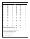
BATT
ON
X
10
X
1
0
5
4
3
2
1
9
8
7
6
0
5
4
3
2
1
9
8
7
6
CHANNELMIC LEVEL
OFF
STAND BY
Lo Hi
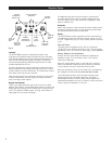
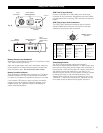
ATW-T102
Input
Connector
Power Switch
(Off/Standby/On)
Battery Condition
Indicator
Microphone
Level Control
Channel Selector
Switches
Fig. D
Plug-on Transmitter Setup
Battery Selection and Installation
Always use a fresh alkaline 9V battery. Turn the Power switch
“Off” before inserting a battery.
Open the hinged battery door. Insert the battery, observing
correct polarity as marked inside the battery compartment.
Close the battery door.
Do not force the door closed.
Battery Condition Indicator
After the battery is installed, turn the power on. The battery
condition indicator LED (Fig. D) should flash momentarily.
If it does not, the battery is installed incorrectly or it is dead.
If the indicator LED stays on (does not flash), the battery
voltage is low and the battery should be replaced. If this
happens during use, replace the battery immediately to
ensure continued operation.
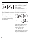
E1
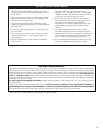
Fig. E
E2
E3
ATW-T102(x) Microphone Input
The ATW-T102(x) plug-on transmitter has a 3-pin XLRF-type
input connector with a locking collar. Use a dynamic
microphone, or a condenser mic with an internal battery. To
attach the microphone, rotate the threaded locking collar
fully
clockwise (“down”) until it reaches the transmitter housing
(Fig. E1). Then rotate the collar back “up” one or two turns to
expose the microphone latch.
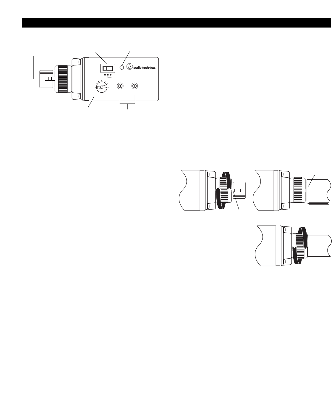
Press the microphone and transmitter together (Fig. E2),
making certain that the latch “clicks” into the base of the mic.
Pull on the mic to make certain it is latched on the connector.
Continue to rotate the threaded collar “up” until it is
firmly
against the end of the mic (Fig. E3). Make certain the mic is
securely attached before use.
To detach the microphone, reverse the steps above.
Always
loosen the threaded collar
fully
before attempting to
disconnect the mic.
Latch
“CLICK”
The ATW-T102(x) provides a bias voltage of +5V on Pins 2
and 3 which will power some “battery/phantom” mics
designed to work at this low voltage. However, the
ATW-T102(x) will not power a “phantom powered” mic which
requires the more-typical 12 to 48 volts. Use of the bias
voltage will reduce battery life slightly. Presence of the bias
voltage will not affect dynamic microphones.
Pin 1 Case Ground
Pin 2 Audio “+” and 5V DC bias
Pin 3 Audio “–” and 5V DC bias
Transmitting Antenna
The ATW-T102(x) plug-on transmitter's antenna is housed in a
non-metallic section between the metal transmitter case and
the mic connector. For best operation, hold the body of the
microphone itself and do not cover or obstruct the antenna
area.