


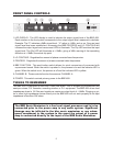
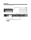

FRONT PANEL CONTROLS
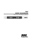
LED DISPLAY: The LED display is used to indicate the output signal level of the BBE 482i.
Each number on the front panel corresponds to the output signal level, measured in decibels.
Example: The “0” indicates a 0dBu signal level, “-6” refers to -6dBu, and so on. Once an input
signal level has been established, increasing the BBE PROCESS and LO CONTOUR will
increase the output signal and cause more LEDs to illuminate. The Clip LED monitors the input
signal level. The Clip LED will illuminate at +15dBu, giving a 3dBu warning of the impending
distortion at +18dBu, the actual clip point.
LO CONTOUR: Regulates the amount of phase corrected bass frequencies.
PROCESS: Regulates the amount of phase corrected treble frequencies.
BBE FUNCTION: This push button switch allows for quick comparison of processed with
unprocessed sound. When the switch is pushed in, the process is on and the indicator LED is
green. When the switch is out, the process is off and the indicator LED is yellow.
CHANNEL B: These controls function the same as CHANNEL A.
POWER: This switch controls primary power to the BBE 482i.
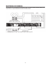
THINGS TO REMEMBER
The BBE 482i is designed to work with -l0dBu line levels. This is suitable for professional and
semi-pro mixers, P.A. consoles, recording studios, or D.J. equipment. The BBE 482i drives load
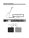
impedances down to 1K Ohm and supplies a maximum output level of +18dBu. Plugging a gui-
tar or other high impedance device directly into the BBE 482i will not work properly as its input
impedance is less than 50K ohms.
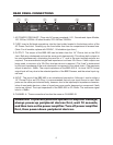
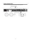
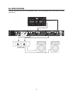
The BBE Sonic Maximizer is a line level signal processor and is to be
connected prior to the power amp in any audio system. Signicant
damage may be inicted to the bbe sonic maximizer or any subse-
quent component in the system in the event the output of a power
amp is connected directly to the input of the BBE Sonic Maximizer.
1.
2.
3.
4.
5.
6.
5