


6
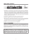
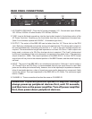
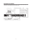
REAR PANEL CONNECTIONS
AC POWER CORD INLET: Plugs into AC power receptacle. U.S., Canada and Japan Models,
100-120Vac, 50/60Hz. All other models, 220~240Vac, 50/60Hz.
FUSE: Insert a at blade screwdriver into the fuse holder located in the bottom portion of the
AC Power Cord inlet. Carefully pry the fuse holder free from its compartment to access fuse.
(Note: For all models, replace with 250VAC, .2A slowblow type fuse.)
OUTPUT: The output of the BBE 482i can be taken from the 1/4” Phone Jack or the RCA
Jack. Both are unbalanced and are the same point electronically. This allows both outputs to
be used simultaneously, eliminating the need for a “Y” cord in the event multiple outputs are
required. The recommended single load impedance is at least 10k Ohms. If both outputs are
being used, a minimum of a 22k Ohm load per device is required. (The “load” is determined
by the input impedance of the next subsequent component in the signal chain.) The maximum
output is rated at +18dBu. The output impedance of the BBE 482i is 1 k ohms. NOTE: Actual
output level will vary due to the selected position of the BBE Process, and the actual input sig-
nal level.
INPUT: The input of the BBE 482i is an unbalanced connection. Although it can be either a
1/4” Phone Plug or an RCA Plug, it is recommended that only one input source is used. Both
jacks are the same point electronically, however, due to the input/output impedance character-
istics of most audio devices, a loss of signal may occur and/or damage to a component if both
inputs are utilized. The input impedance of the BBE 482i is 47k Ohms. The maximum signal
level is +18dBu.
CHANNEL A: These connections function the same as CHANNEL B.
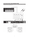
WARNING! To prevent possible speaker or amplier damage,
always power-up peripheral devices rst, wait 10 seconds,
and then turn on the power amplier. Turn off power amplier
rst, then power-down peripheral devices.
1.
2.
3.
4.
5.