


6 XENYX 1204FX/1204 User Manual
Online registration1.3.3
Please register your new BEHRINGER equipment right after your purchase
by visiting http://behringer.com and read the terms and conditions of our
warranty carefully.
Should your BEHRINGER product malfunction, it is our intention to have it
repaired as quickly as possible. To arrange for warranty service, please contact
the BEHRINGER retailer from whom the equipment was purchased. Should your
BEHRINGER dealer not be located in your vicinity, you may directly contact
one of our subsidiaries. Corresponding contact information is included in the
original equipment packaging (Global Contact Information/European Contact
Information). Should your country not be listed, please contact the distributor
nearest you. A list of distributors can be found in the support area of our website
(http://behringer.com).
Registering your purchase and equipment with us helps us process your repair
claims more quickly and efficiently.
Thank you for your cooperation!
Control Elements and Connectors 2.
This chapter describes the various control elements of your mixing console.
All controls, switches and connectors will be discussed in detail.
Mono channels2.1
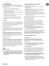
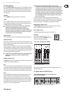
Microphone and line inputs 2.1.1
MIC
Each mono input channel offers a balanced
microphone input via the XLR connector and also
features switchable +48 V phantom power supply for
condenser microphones. The XENYX preamps provide
undistorted and noise-free gain as is typically known
only from costly outboard preamps.
Please mute your playback system before ◊
you activate the phantom power supply to
prevent switch-on thumps being directed
to your loud speakers. Please also note the
instructions in chapter 2.4.2 “Voltage supply,
phantom power and fuse”.
LINE IN
Each mono input also features a balanced line input on a ¼" connector.
Unbalanced devices (mono jacks) can also be connected to these inputs.
Please remember that you can only use either the microphone ◊
or the line input of a channel at any one time. You can never use
both simultaneously!
LOW CUT
The mono channels of the mixing consoles have a high-slope LOW CUT filter for
eliminating unwanted, low-frequency signal components (75 Hz, 18 dB/octave).
GAIN
Use the GAIN control to adjust the input gain. This control should always be
turned fully counterclockwise whenever you connect or disconnect a signal
source to one of the inputs.
Fig. 2.1: Connectors and
controls of mic/line inputs
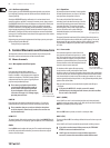
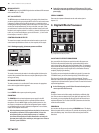
Equalizer2.1.2
All mono input channels include a 3-band equalizer.
All bands provide boost or cut of up to 15 dB. In the
central position, the equalizer is inactive.
The circuitry of the British EQs is based on the
technology used in the best-known top-of-the-line
consoles and providing a warm sound without any
unwanted side effects. The result are extremely
musical equalizers which, unlike simple equalizers,
cause no side effects such as phase shifting or
bandwidth limitation, even with extreme gain
settings of ±15 dB.
The upper (HI) and the lower band (LO) are shelving filters that increase or
decrease all frequencies above or below their cut-off frequency. The cut-off
frequencies of the upper and lower band are 12 kHz and 80 Hz respectively.
The mid band is configured as a peak filter with a center frequency
of 2.5 kHz.
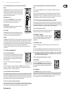
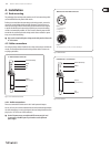
Aux sends2.1.3
Aux sends take signals via a control from one or
more channels and sum these signals to a so-called
bus. This bus signal is sent to an aux send connector
and then routed, for example, to an active monitor
speaker or an external effects device. The return from
an external effect can then be brought back into the
console via the aux return connectors.
For situations which require effects processing,
the aux sends are usually switched post-fader so that
the effects volume in a channel corresponds to the position of the channel fader.
If this were not the case, the effects signal of the channel would remain audible
even when the fader is turned to zero. When setting up a monitor mix, the aux
sends are generally switched to pre-fader; i.e. they operate independently of the
position of the channel fader.
Both aux sends are mono, are sourced after the equalizer and offer up to
+15 dB gain.
If you press the MUTE/ALT 3-4 switch, aux send 1 is muted, ◊
provided that it is switched post-fader. However, this does not affect
the aux send 2 of the 1204FX.
AUX 1 (MON)
In the 1204FX, aux send 1 can be switched pre-fader and is thus particularly
suitable for setting up monitor mixes. In the 1204, the first aux send is labeled
MON and is permanently switched pre-fader.
PRE
When the PRE switch is pressed, aux send 1 is sourced pre-fader.
AUX 2 (FX)
The aux send labeled FX is for sending to effects devices and is thus set up to be
post-fader.
In the 1204FX, the FX send is routed directly to the built-in effects processor.
If you wish to use the internal effects processor, the STEREO AUX ◊
RETURN 2 connectors should not be in use.
1204FX: you can also connect an external effects processor to ◊
aux send 2, however the internal effects module will be muted.
Fig. 2.2: The equalizer
of the input channels
Fig. 2.3: The AUX SEND
controls in the channel strips