


9 XENYX 1204FX/1204 User Manual
CD/TAPE TO MAIN
When the CD/TAPE TO MAIN switch is depressed, the 2-track input is routed to
the main mix and thus serves as an additional input for tape machines. You can
also connect MIDI instruments or other signal sources here that do not require
any further processing. At the same time, this switch disables the main mix to
tape output link.
POWER
The blue POWER LED indicates that the device is switched on.
+48 V
The red “+48 V” LED lights up when the phantom power supply is switched
on. The phantom power supply is necessary for condenser microphones and is
activated using the switch on the rear of the device.
Please do not connect microphones to the mixer (or the stagebox/◊
wallbox) while the phantom power supply is switched on.
Connect micro-phones before you switch on the power supply.
In addition, the monitor/PA loudspeakers should be muted before you
activate the phantom power supply. After switching on, wait approx.
one minute to allow for system stabilization.
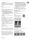
LEVEL METER
The high-precision level meter accurately displays the appropriate signal level.
LEVEL SETTING:
When recording to a digital device, the recorder’s peak meter should not exceed
0 dB. This is because, unlike analog recordings, slightly excessive levels can create
unpleasant digital distortion.
When recording to an analog device, the VU meters of the recording machine
should reach approx. +3 dB with low-frequency signals (e.g. kick drum). Due to
their inertia VU meters tend to display too low a signal level at frequencies above
1 kHz. This is why, for example, a Hi-Hat should only be driven as far as -10 dB.
Snare drums should be driven to approx. 0 dB.
The peak meters of your XENYX display the level virtually independent ◊
of frequency. A recording level of 0 dB is recommended for all
signal types.
MODE (1204FX only)
The MODE switch determines whether the channels’ SOLO switch operates as PFL
(Pre Fader Listen) or as solo (Solo In Place).
PFL
To activate the PFL function, depress the MODE switch. The PFL function should,
as a rule, be used for gain setting purposes. The signal is sourced pre-fader and
assigned to the mono PFL bus. In the “PFL” setting, only the left side of the peak
meter operates. Drive the individual channels to the 0 dB mark of the VU meter.
Solo
When the MODE switch is not depressed, the stereo solo bus is active. Solo is
short for “Solo In Place”. This is the customary method for listening to an
individual signal or to a group of signals. As soon as a solo switch is pressed,
all channels in the control room (and headphones) that have not been selected
are muted thereby retaining stereo panning. The solo bus can carry the output
signals of the channel pan controls, the aux sends and the stereo line inputs.
The solo bus is, as a rule, switched post-fader.
The PAN control in the channel strip offers a constant power ◊
characteristic. This means that the signal is always at a constant level,
irrespective of its position in the stereo panorama. If the PAN control
is moved fully left or right from center, the level increases by 4 dB in
that channel. This ensures that, when set in the center, the audio signal
is not louder. For this reason, with the solo function activated (Solo in
Place), audio signals from the channels with PAN controls that have not
been moved fully to the left or right are displayed at a lower volume
than in the PFL function.
As a rule, solo signals are monitored via the control room outputs and
headphones connector and are displayed by the level meters. If a solo switch is
pressed, the signals from the tape input, Alt 3-4 and main mix are blocked from
the control room outputs, the headphone connector and the level meter.
MAIN SOLO (1204FX only)
The MAIN SOLO LED lights up as soon as a channel or aux send solo switch is
pressed. The MODE switch also has to be set at “Solo”.
PFL (1204FX only)
The PFL LED indicates that the peak meter is set to PFL mode.
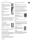
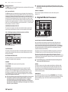
PHONES
You can connect headphones to this ¼" TRS
connector. The signal on the PHONES connection is
sourced from the control room output.
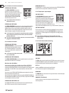
Alt 3-4 and main mix fader2.3.7
Fig. 2.13: Alt 3-4 and main mix fader
Use the high-precision quality faders to control the output level of the Alt 3-4
subgroup and main mix.
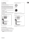
Rear view of 1204FX/12042.4
Main mix outputs, Alt 3-4 outputs and 2.4.1
control room outputs
Fig. 2.14: Main mix outputs, Alt 3-4 outputs and control room outputs
Fig. 2.12: PHONES connector