


6 EUROLIVE B1520DSP User Manual
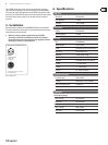
2. Control Elements and Connections
(1)
(2) (7) (8) (9) (4)
(10) (11) (12) (13) (6) (5)
(3)
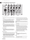
Fig. 2.1: Control elements and connections
(1) Power is supplied via an IEC connector. The matching cable is provided with
the unit.
(2) Use the POWER switch to turn on the B1520DSP. Before connecting the unit
to the power mains, ensure that the POWER switch is in OFF position.
◊ Attention: The POWER switch does not fully disconnect the unit
from the mains. To disconnect the unit from the mains, pull out the
main cable plug or appliance coupler. When installing the product,
ensure the plug or appliance coupler is readily operable. Unplug the
power cord completely when the unit is not used for long periods
of time.
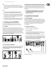
(3) Use the LEVEL control to adjust the signal gain of the MIC/LINE inputs.
Before you connect or disconnect a signal source to or from one of the inputs,
please turn the corresponding control fully to the left. Once the signal
source is connected, increase the volume as desired by turning the control
clockwise. Always make sure that the CLIP LED (4) does not light up at all or
with signal peaks only.
Line-level signals:
Devices with high output levels (e.g. the outputs of mixing consoles or
CD players) only need little gain. In this case, the LEVEL control will mostly
be positioned somewhere in the area marked “LINE” (left half of the
control range).
Microphone signals
Low-level microphone signals need more gain. When microphones are used,
the control will be positioned in the MIC area (right half of the control range).
◊ We would like to draw your attention to the fact that extremely loud
sound levels may damage your hearing as well as your headphones/
loudspeakers. Turn the LEVEL control fully to the left before you switch
on the unit. Be careful to select a suitable volume at all times.
(4) The CLIP LED lights up when the input signal level is too high. In this case,
turn the LEVEL control (3) to the left until the LED goes out or only lights up
at peak levels.
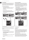
(5) Use the MIC/LINE inputs (XLR connectors) for connecting audio signals.
(6) The LINE OUT XLR jack provides the signal with no additional gain applied
in order to connect another loudspeaker, for example. The output signal is a
mix of both input signals. (See Chapter 4.2 for more information on how to
use several loudspeakers)
The B1520DSP is equipped with a 2-band tone control. Each band allows you to
apply a maximum boost/cut of 15 dB, in its center position the equalizer is set
to neutral.
(7) Use the EQ HIGH control to cut or boost the treble range by 15 dB. The cut-o
frequency is 12 kHz.
(8) Use the EQ LOW control to cut or boost the bass range by 15 dB. The cut-o
frequency is 100 Hz.
(9) The B1220DSP features a high-pass lter with a slope of 24 dB/oct. to
eliminate unwanted low-frequency content, such as pop sounds produced
by hand-held microphones, or rumble or wind noise when using high-
sensitivity microphones. The LOW CUT control adjusts the cut-o frequency.
If you want to use the B1520DSP in combination with a subwoofer,
youcan use the high-pass lter to lower the bass range reproduced by
the subwoofer. This allows you to operate the B1520DSP even without
an external frequency crossover. Set the cut-o frequency to the highest
frequency that can be reproduced by the subwoofer.
(10) The CONTOUR switch governs the dynamic contour lter:
SPEECH
Setting the CONTOUR switch to SPEECH (switch not pressed) will
optimize the frequency response for speech applications. This ensures
better intelligibility.
MUSIC
Setting the CONTOUR switch to MUSIC (switch pressed) will optimize the
frequency response for music playback.
(11) The TIMED TURNOFF switch activates the automatic turn-o function: