


behringer.com
12 EURODESK SX2442FX/SX3242FX User Manual
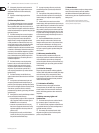
These selector switches route the eect signal to the main mix or to the [65]
subgroups 1-2 or 3-4. If the MAIN/SUB switch is not pressed, the eect
signal is sent to the main mix and the SUB 1/2 / SUB 3/4 switch below
is inoperative. If the upper switch is pressed (SUB), however, the lower
switch determines whether the eect signal is routed to subgroups 1 and 2
(SUB 1/2) or 3 and 4 (SUB 3/4).
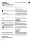
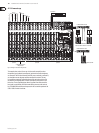
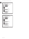
[67] [66]
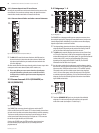
Fig. 2.26: FX send and return connectors
The [66] FX SEND 1 and 2 connectors also provide the master FX send signals,
for example, to connect them to the inputs of an external eects device.
However, these are “dry” signals only with no “eect signals” from the
built-in eects processor!
The Stereo [67] FX RETURN inputs 1 and 2 return the eect signals from external
eects processors and add them to the main mix.
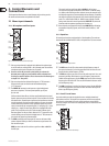
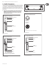
[68]
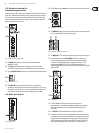
Fig. 2.27: Footswitch connectors
The [68] FOOTSW(ITCH) connector allows you to connect a standard dual
footswitch to separately enable/disable FX 1 or FX 2. The tip of the ¼" plug
controls FX 1, the ring controls FX 2.
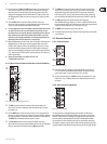
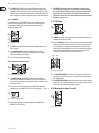
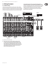
Rear panel2.11
[72] [71] [69] [70] [73]
Fig. 2.28: The rear panel of the EURODESK
Use the [69] POWER switch to put the mixer into operation. This switch should
always be in the “O” position when you connect your unit to the mains.
Please note: The POWER switch does not fully disconnect the unit from ◊
the mains. To disconnect the unit from the mains, pull out the main
cord plug or appliance coupler. When installing the product, ensure the
plug or appliance coupler is readily operable. Unplug the power cord
when the unit is not used for prolonged periods of time.
With the [70] PHANTOM switch you can activate the phantom power supply
for the XLR connectors of the mono channels for condenser microphones.
The +48 V-LED [37] illuminates when phantom power is on. In most cases,
dynamic microphones can still be used as long as they are connected in
a balanced conguration. If in doubt, please contact the manufacturer of
your microphone!
The mains connection is a standard IEC receptacle. An appropriate power [71]
cord is supplied with the unit.
FUSE HOLDER[72] . Before connecting the unit to the mains, ensure that
the voltage setting matches your local voltage. Blown fuses should only
be replaced by fuses of the same type and rating. Please also read the
information given in chapter 6 “Specications”.
SERIAL NUMBER[73] .
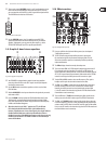
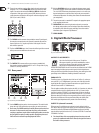
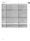
Digital Eects Processor3.
Fig. 3.1: List of all eects presets
99 FIRST-CLASS PRESETS
Here is the list of all multi-eects presets. The built-in
eects processor oers you various standard eects such as
reverb, chorus, anger, delay and a variety of combination
eects from our renowned studio eects processor
VIRTUALIZER PRO DSP2024P. Use the FX control on the channels and the FX SEND
control to supply the eects processor with signals. A built-in digital stereo
eects processor has the benet of no external wiring, thus reducing the risk of
ground loops or level dierences. Handling is therefore much easier.
PARALLEL FX
The eects presets 1 to 70 provide classic “add-to-mix” eects. So, when you
turn up the FX 1 (or 2) TO MAIN control, you create a mix of the (dry) channel
signal and the eect signal. The balance between the two signals can be set
with the FX send and FX 1/2 TO MAIN controls.
This also applies to adding eect signals to the AUX 1 (or 2) monitor mix, with the
exception that the mix here is adjusted with the AUX 1 (or 2) control in the
channel strip and the FX TO AUX 1 (or 2) potentiometer. Of course, the eects
processor must receive a signal from the channel using the FX 1 (or 2) control.
Make sure that the PRE switch in the corresponding channel strip(s) is pressed.
Otherwise, the AUX buses will be set post-fader making the volume of the
AUX monitor signal dependent on the position of the channel fader(s).
INSERT FX (channel is muted)
Eects presets #71 and higher process the entire signal, unlike the “add-to-
mix” eects. When you use an insert preset, be sure to separate the respective
channel from all buses (SUB button and MAIN button not pressed) and only
route the eect signal to the main mix (FX 1/2 control, FX SEND 1/2 control and
FX TO MAIN 1/2 control).
The channel fader of the corresponding channel remains active and ◊
governs (in combination with the FX controls) the signal level sent to
the built-in effects processors.