


behringer.com
6 EURODESK SX2442FX/SX3242FX User Manual
Control Elements and 2.
Connections
This chapter describes the various control elements of your mixing console.
All controls and connections are explained in full detail.
Mono input channels2.1
Microphone and line inputs2.1.1
[1]
[2]
[3]
[4]
[5]
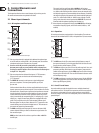
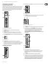
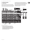
Fig. 2.1: Connectors and controls of the mic/line inputs
Each mono input channel is equipped with a balanced microphone input [1]
on an XLR connector, which provides +48 V phantom power for condenser
microphones at the touch of a button (see rear panel).
Be sure to switch off your audio system before you activate the ◊
phantom power supply to prevent audible switch-on thumps from
reaching your monitor speakers. Please also note the information given
in chapter 2.11 “Rear panel”.
Each mono input also has a balanced line input on ¼" TRS connectors. [2]
Of course, these inputs can also be used with unbalanced plugs
(¼" TS connector).
The [3] INSERT I/O connector is used to process a signal with dynamic
processors or equalizers. This insert point isprefader, pre-EQ and
pre-aux send.
Unlike reverb and other eects, which are usually added to the dry signal,
dynamic processors process the entire signal. So, aux send buses are not the
best solution here. Instead, dynamic processors and equalizers are inserted
into the signal path. Once processed, the signal then re-enters the mixing
console at the same point where it left. Signal interruption only occurs if
a plug is inserted into the corresponding jack (¼" stereo plug: tip = signal
output, ring = input). All mono input channels are equipped with insert
points. They can also be used as pre-EQ direct outputs, without signal
ow interruption. For this you need a cable with a ¼" TS connector on the
recorder/eects processor end, and a bridged stereo ¼" TRS connector on
the console end (tip and ring interconnected).
The [4] GAIN control adjusts the input gain. Be sure to set this control fully
counter-clockwise before you connect or disconnect a signal source to or
from one of the inputs.
GAIN has a dual scale: the rst scale has a gain from +1 0 to +60 dB for
the MIC input.
The second scale has a gain from +1 0 to -40 dBu for the line input.
For devices with a nomal line output level of-10 dBV or +4 dBu the setting
is as follows: with GAIN fully counter-clockwise connect the external device
and adjust the output level recommended by the manufacturer. If available,
the output level display of the external device should read 0 dB with signal
peaks. For +4 dBu increase GAIN, for -10 dBV increase it further. The ne-
tuning can be done with a music signal and the LEVEL SET LED, which will
illuminate when the optimum operating level has been set.
Mono channels are equipped with a high-slope [5] LOW CUT lter eliminating
unwanted low-frequency signals, such as oor rumble (18 dB/oct., -3 dB
at 80 Hz).
Equalizer2.1.2
All mono input channels are equipped with a 3-band equalizer. The maximum
boost/cut of the individual bands is 15 dB, in mid position the EQ is set to neutral.
[6]
[7]
[8]
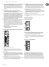
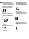
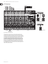
Fig. 2.2: Equalizer section of input channels
The [6] HIGH control in the EQ section controls the high frequency range of
the respective channel. It is a shelving-type lter which can boost or cut all
frequencies above a xed frequency (12 kHz).
The [7] MID control allows you to raise or lower the mid-range level. It is a semi-
parametric peak lter, which boosts or cuts the frequency range around a
variable mid-range frequency. Use the FREQ control to select the mid-range
frequency from 100 Hz to 8 kHz. Then use the MID control to boost or cut the
selected frequency range.
The [8] LOW control boosts or cuts the low-frequency range. Like the HIGH lter
it is a shelving-type lter, which raises or lowers the level of all frequencies
below a specic frequency (80 Hz).
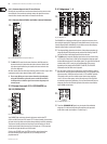
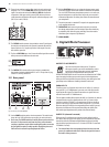
Aux/FX send buses2.1.3
Aux sends enable you to take the signals from one or multiple channels and
collect them on one bus. This signal is then present at one of the aux send jacks,
from where it can be routed to an active monitor speaker or external eects
device, for example. The FX returns are subsequently used as a return bus for the
processed signal.
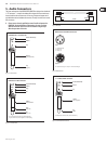
[9]
[11]
[10]
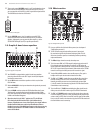
Fig. 2.3: AUX/FX send controls in the channel strips