


13
V-TONE GMX110/GMX210/GMX212/GMX1200H
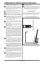
6.2 Speaker connection
The GMX110 features a SPEAKER connector to which you
can connect an additional loudspeaker. This additional loud-
speaker should be able to handle at least 30 Watts and the
impedance of 4 Ω.
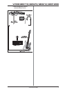
The GMX212 and GMX1200H feature two LOUDSPEAKER-
outputs (EXT LEFT and EXT RIGHT) for connecting two
loudspeakers or a single stereo loudspeaker unit. The output
power rating is 60 W per channel. To assure optimal power
delivery from the amp, you should use 8-Ω loudspeakers that
can handle at least 60 Watts.
This goes for all models: You can also use loudspeakers with
higher impedance values, but this lowers proportionally the power
delivery as the resistance increases. Doubling the impedance
halves the power value (double the Ohms = half the Watts).
+ Since SPEAKER and LOUDSPEAKER outputs are
connectors where amplified signals are given out,
never connect equipment with line-level inputs to
these two connectors, e. g. mixer inputs.
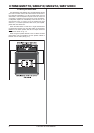
6.3 MIDI connection
The MIDI standard (Musical Instruments Digital Interface) was
first developed at the beginning of the 80s, with the goal of
enabling mutual communication between electronic instruments
of various manufacturers. Over the years, the number of possible
MIDI applications has increased substantially; nowadays, it is
perfectly normal to connect entire studios via MIDI.
At the center of this network is a computer with a sequencing
software, used to control not only keyboards but also effects
processors and other peripheral equipment. In such a studio,
you can control your V-TONE in real time from a computer. Using
a MIDI footswitch presents itself as a great idea, especially in
live applications, because it allows you to control not only effect
parameters but also switch between channels and effects.
The standard 5-pole DIN MIDI connector is located on the rear
of your V-TONE. To connect your V-TONE with other MIDI
equipment, you will need a MIDI cable. Pre-packed cables
available at music stores are used for this purpose. Such cables
should not be longer than 15 m (45 ft).
MIDI IN receives MIDI control data. The receiving channel is
adjusted using the CHANNEL and IN/OUT key combination On =
Omni means that MIDI data are being received and processed on
all channels (compare section 4.2).
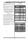
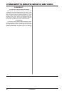
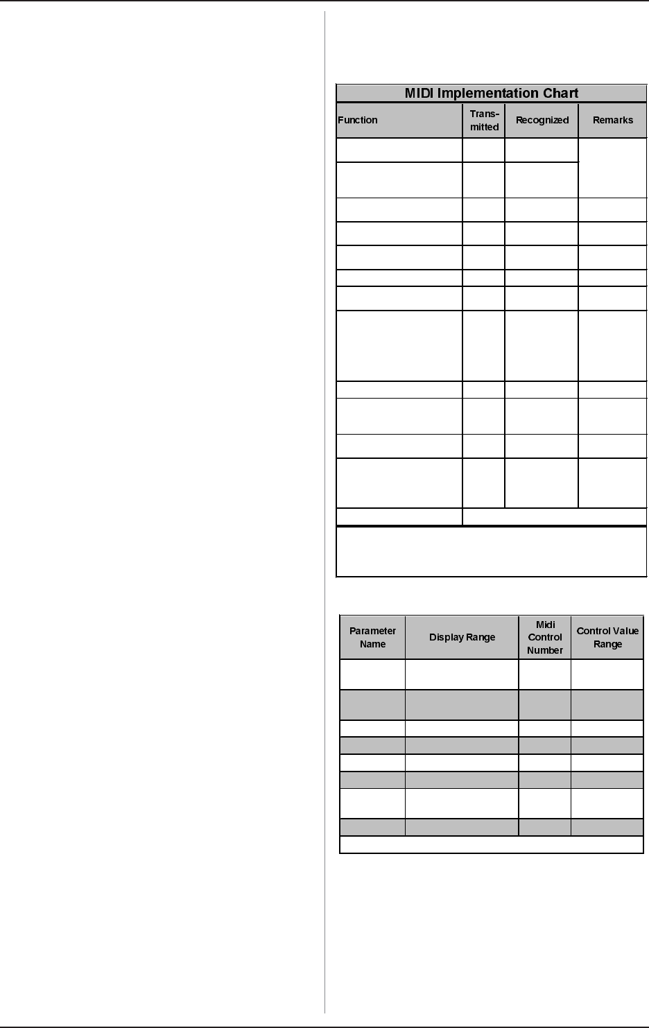
7. APPENDIX
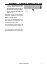
7.1 MIDI implementation
Basic
Channel
Default
Changed
X
X
OFF, 1 - 16
OFF, 1 - 16
memorized
Mode
Default
Messages
Altered
X
X
X
1,2
X
X
Note
Number
True Voice
X
X
X
X
Velocity
Note ON
Note OFF
X
X
X
X
After
Touch
Keys
Channels
X
X
X
X
Pitch Bender X X
Control X
O 7, 10 - 15,
18
see add. table
Progr.
Change
True #
X
O 122, 123,
124, 127
(0 - 98)
1 - 99
122 = TUNER
123 = CLEAN
124 = DRIVE
127 = Effect
Bypass
XX
System
Common
Song Pos.
Song Sel.
Tune
X
X
X
X
X
X
System
Real Time
Clock
Commands
X
X
X
X
Aux
Messages
Local ON/OFF
All notes OFF
Active Sense
Reset
X
X
X
X
X
X
X
X
Notes
O = YES, X = NO
Mode 1: OMNI ON
Mode 2: OMNI OFF
System Exclusive
Tab. 7.1: MIDI implementation
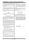
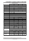
Volume
Controller
- 7 0 .. 127
Channel
CLEAN (Channel 1) = 0
DRIVE (Channel 2) = 1
10 0 .. 1
Effect OFF = 0, ON = 1 11 0 .. 1
Parameter 1 depends on effect * 12 0 .. 127 (max.
)
Parameter 2 depends on effect * 13 0 .. 127 (max.
)
Parameter 3 depends on effect * 14 0 .. 127 (max.
)
Wah/
Modulation
- 15 0 .. 127
Store Enable - 18 0 .. 127
* for details see Tab. 4.1
Tab. 7.2: V-TONE MIDI controllers
7. APPENDIX