


11
COMPOSER PRO MDX2200
13
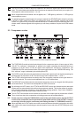
Using the SC MON switch will enable you to connect the side chain control signal to the audio output,
whilst at the same time muting the audio input. This function provides you with the ability to monitor the
side chain signal that is returned via inserted equalizers or other external processors. The SC MONITOR
function will assist you with tuning equalizer parameters for example.
+ Please note when the SC MON switch is engaged, the audio processing facility of the respec-
tive channel is disabled. When this function is active, a visual indication will be provided by
the switches LED, which will blink.
14
The IN/OUT switch activates the relay and hence the corresponding channel. This switch acts as a so-
called hard-bypass relay, which means that when the switch is OUT or when the unit is disconnected
from the mains, the input jack is directly linked to the output jack. Normally, this switch is used to
perform a direct A/B comparison between the unprocessed and the compressed or limited signals.
15
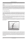
Press the INTERACTIVE switch to change from hard knee to IKA characteristics. IKA provides a very
subtle and musical compression of the program material and should therefore be used whenever
compression should be more or less inaudible.
16
The SC FILTER switch activates a high-pass filter in the side-chain path and thus limits the influence of
low frequencies on the COMPOSER PROs control processes.
17
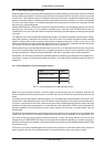
The 12-digit GAIN REDUCTION meter indicates how effectively the gain is reduced by the compressor,
within a range from 1 to 30 dB.
18
The 12-digit INPUT/OUTPUT LEVEL meter informs youdepending on the setting of the I/O METER
switchabout the current input or output level, within a range from -30 to +18 dB. When the switch is
set to IN (engaged), the meter reads the input level, when it is OUT (not engaged), the output level is
displayed. The meter is referenced to the operating level (-10 dBV or +4 dBu) adjusted with the
OPERATING LEVEL switch.
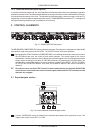
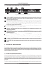
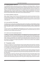
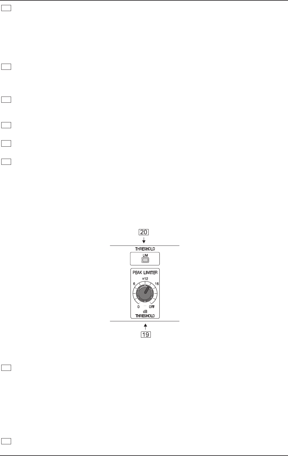
2.3 Peak limiter section
Fig. 2.4: Control elements of the peak limiter section
19
The peak limiter limits the signal to a level adjusted with the THRESHOLD control. Owing to its
extremely fast response (zero attack), the limiter is capable of limiting signal peaks without audible
distortion. Whenever the signal is limited for more than 20 ms, the overall level is reduced for about
1 second to avoid heavy and thus audible signal distortion.
+ When you use the peak limiter as a protective device against signal peaks, the THRESHOLD
control should be set in combination with the OUTPUT control in the compressor section so
that the peak limiter responds rarely or not at all. Thus, only real signal peaks will activate the
limiter circuit. However, to produce creative sound effects, the peak limiter can be
deliberately set to lower levels.
20
The LIM LED lights up as soon as the limiter function is activated.
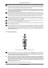
2. CONTROL ELEMENTS