


12
COMPOSER PRO MDX2200
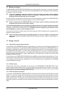
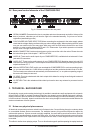
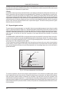
2.4 Rear panel control elements of the COMPOSER PRO
Fig. 2.5: Control elements of the rear panel
21
SERIAL NUMBER. Please take the time to complete and return the warranty card within 14 days of the
date of purchase, otherwise you will lose the right to the extended warranty. Or just use our online-
registration (www.behringer.com).
22
FUSE HOLDER/VOLTAGE SELECTOR. Before connecting the equipment to the mains supply, please
check that the voltage display conforms with your mains voltage supply. When replacing the fuse, make
sure you use another one of the same type. With many units the fuse holder can be set in one of two
positions, in order to switch between 230 V and 115 V. Please note: if you wish to operate a unit outside
Europe, then a stronger fuse must be used.
23
MAINS CONNECTION. Use the enclosed power cord to connect the unit to the mains. Please also note
the instructions given in the chapter 7. INSTALLATION.
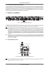
24
AUDIO IN. These are the audio inputs of your COMPOSER PRO, available both as balanced 6.3 mm
jack and XLR connectors.
25
AUDIO OUT. These are the audio outputs of your COMPOSER PRO. Matching phone jack and XLR
connectors are wired in parallel. These outputs can be transformer-balanced by retrofitting the optional
output transformer OT-1.
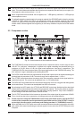
26
With the OPERATING LEVEL switch you can adapt the COMPOSER PRO to various operating levels,
i.e. you can select both the -10 dBV home recording level and the professional studio level of +4 dBu.
The level meters are referenced automatically to the selected level, i.e. an optimum operating range of
the meters will always be ensured.
27
SC SEND. This is the unbalanced side-chain output which allows for routing the audio signal to external
processing devices.
28
SC RETURN. This is the unbalanced side-chain input used to return any external or processed control
signal.
3. TECHNICAL BACKGROUND
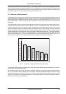
By employing current modern analog technology it is possible to manufacture audio equipment with a dynamic
range of up to 125 dB. In contrast to analog techniques, the dynamic range of digital equipment is approxi-
mately 25 dB less. With conventional record and tape recorder technology, as well as broadcasting, this value
is further reduced. Generally, dynamic restrictions are due to noisy storage in transmission media and also the
maximum headroom of these systems.
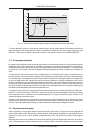
3.1 Noise as a physical phenomenon
All electrical components produce a certain level of inherent noise. Current flowing through a conductor leads
to uncontrolled random electron movements. For statistical reasons, this produces frequencies within the
whole audio spectrum. If these currents are highly amplified, the result will be perceived as noise. Since all
frequencies are equally affected, we term this white noise. It is fairly obvious that electronics cannot function
without components. Even if special low-noise components are used, a certain degree of basic noise cannot
be avoided.
This effect is similar when replaying a tape. The non-directional magnetic particles passing the replay head can
3. TECHNICAL BACKGROUND