


10 ULTRAGAIN PRO MIC2200 User Manual
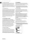
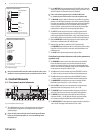
4.2 Rear panel control elements
(16)
(17) (19) (18)
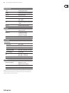
Fig. 4.2: Rear panel elements of the ULTRAGAIN PRO
(16) FUSE HOLDER / VOLTAGE SELECTOR. Please make sure that your local
voltage matches the voltage indicated on the unit, before you attempt to
connect and operate the ULTRAGAIN PRO. Blown fuses may only be replaced
by fuses of the same type and rating.
(17) MAINS CONNECTION. Use the enclosed power cord to connect the unit
to the mains. Please also note the instructions given in the “Installation”
chapter.
(18) AUDIO IN. These are the audio inputs of your ULTRAGAIN PRO. The XLR
connector is the common mic/line input. The line input is based on
jackconnection.
(19) AUDIO OUT. These are the audio outputs of your ULTRAGAIN PRO.
Matchingphone jack and XLR connectors are wired in parallel.
5. Applications
This section describes some typical applications of the BEHRINGER ULTRAGAIN
PRO. Starting from the following basic settings you can use it to solve the
majority of audio problems.
Please take your time to study the application examples, so as to be able to fully
exploit the ULTRAGAIN PRO and its variety of features.
Basically, the ULTRAGAIN PRO can be used in ve areas of application:
1. Using the ULTRAGAIN PRO as a high-quality microphone preamp.
2. Using the ULTRAGAIN PRO to convert home recording to studio levels,
andvice versa.
3. Using the ULTRAGAIN PRO to balance unbalanced signals (DI box).
4. Using the ULTRAGAIN PRO as a parametric equalizer specically “tweaking”
the frequency response.
5. Using the ULTRAGAIN PRO to enhance the sound of the program material by
adding “tube warmth”.
5.1 The ULTRAGAIN PRO as a
microphonepreamplier
Before you can use the BEHRINGER ULTRAGAIN PRO as a preamp, we recommend
that you study the various functions of the device. The high gain factors provided
by the microphone preamp can produce extreme levels on the output side,
which may damage subsequent devices. So, you should start with the following
basicsetting:
5.1.1 Basic setting
Control elements position
+48 V switch OUT
MIC GAIN control 10 dB
MIC/LINE switch LINE
PHASE REV. Control OUT
LO CUT switch OUT
EQ IN/OUT switch OUT
OUTPUT control 0 dB
Tab. 5.1: Basic setting of the ULTRAGAIN PRO
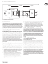
Reduce the volume level of the subsequent audio system to a minimum,
andconnect a microphone to the XLR input connector on the BEHRINGER
ULTRAGAIN PRO. Use either the jack or XLR output connectors to connect the
audio system. Owing to its output-side servo balancing circuit, the ULTRAGAIN
PRO detects whether you use a balanced or unbalanced conguration and adjusts
the levelinternally.
Now, power up the entire equipment and press the MIC/LINE switch to activate
the microphone preamp. If you wish to use a condenser mic requiring +48 V
phantom power, please press the +48 V switch (to avoid electrical damage,
please read chapter 5.1.5 “+48 V switch” below).
5.1.2 MIC GAIN control
Congure the equipment according to the application on hand, speak into
the microphone and turn the GAIN control clockwise until the 0 dB LED lights
up. If your DAT recorder, mixing console or other subsequent devices have
high-precision level meters, you can use these to verify the correct level setting.
The maximum output level depends on the device that follows next in the audio
chain, and must therefore be set specically. The high-precision level meter on
the ULTRAGAIN PRO indicates the current operating level. The CLIP LED lights
up at a level of +18 dBu signaling that you have an additional headroom of
5dB available, before the microphone preamp starts overloading. If distortion/
overloading occurs at high volume levels, you should reduce the gain with the
MIC GAIN control.
5.1.3 PHASE REV. switch
The PHASE REV. switch reverses the audio signal’s phase by 180°. Usually,you won’t
need this switch. However, in some cases, it might be necessary to reverse the signal
phase, for example, if a microphone cable has been connected incorrectly (pins 2
and 3 interchanged), or if several microphones are used and specic circumstances
with regard to room acoustics are causing problems (e.g.frequency cancellations
are usually caused by phase problems). The phase reverse function will help you
locate and eliminate any such problem.
5.1.4 LO CUT function
When you pick up acoustic signals with microphones, it is usually necessary
to eliminate low-end signal portions, such as rumble or pop noise, or other
interference frequencies. Often, such frequencies have very high amplitudes and
do not only deteriorate the sound quality but can also damage the power amps or
speakers. Your ULTRAGAIN PRO features a tunable high-pass lter with a very
high slope. Press the LO CUT switch and adjust the FREQUENCY control, so that
any disturbing frequencies are faded out as much as possible, with the least
damage done to the actual audio signals. Press/release the LO CUT switch several
times to make an A/B comparison.