


7 ULTRAGAIN PRO MIC2200 User Manual
1.3.2 Design and functional principle of tubes
Tubes can be roughly classied according to the number of electrodes they use.
There are tubes with two, three or ve electrodes usually referred to as diodes,
triodes or pentodes.
vacuum
anode
cathode
heating
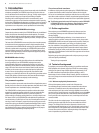
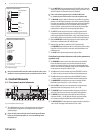
Fig. 1.3: diode
The diode contains two electrodes in a vacuum glass bulb that have electrical
connection to the outside. The vacuum allows for a free movement of electrons.
When one of the electrodes is heated up (= thus becoming a cathode), it begins
to emit electrons. When a positive DC voltage is applied to the other electrode
(= anode), the negative electrons start to migrate from the cathode to the
anode. With reverse polarity between cathode and anode, a current ow is not
possible because the unheated anode emits more or less no electrons. Thisdesign
was used, for example, as a rectier in the power supplies of ampliers.
Themagnitude and velocity of the ow of electrons depend on the cathode’s
temperature, the material it consists of, and the magnitude of the anode voltage.
When the electrons hit the anode they produce heat that is dissipated by using
large anode plates.
vacuum
anode
grid
cathode
heating
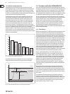
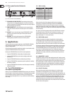
Fig. 1.4: triode
The triode has an additional metal grid between anode and cathode.
Byapplying a negative voltage, this grid can be used to control the internal
resistance of the tube, and hence the anode current. When the grid bias voltage
(voltagebetween cathode and grid) becomes negative, the current owing to
the anode is reduced because the negatively charged grid repels the arriving
electrons. As a consequence, there are less electrons to reach the anode.
Whenthe bias voltage is raised towards zero, the ow of electrons accelerates.
Whenit nally becomes zero or even positive, the grid current begins to ow
which considerably reduces the current owing to the anode and can possibly
destroy the tube. Triodes are most commonly used in preamps, often in pairs
arranged in one tube (twintriode).
vacuum
anode
suppressor grid
screen grid
control grid
cathode
heating
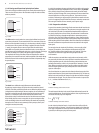
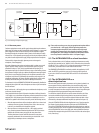
Fig. 1.5: pentode
In a triode the capacitance between grid and anode is a problem with regard to
high frequencies and large amplication factors. For this reason, the pentode
has a positively charged screen grid between the control grid and the anode.
However, the positive charge of the screen grid attracts electrons emitted from
the anode plate when it is hit by arriving electrons. To prevent this electron
emission, a decelerating or suppressor grid is placed between anode and screen
grid. As it is negatively charged it blocks the electrons, so that they cannot reach
the screen grid. Pentodes are most commonly used in power stages.
1.3.3 Properties of tubes
In general, the saturation (overdriving) of both transistor and tube-based circuits
results in various types of distortion. These phenomena are quite complex in the
real world, but for the sake of a straightforward mathematical description we
are going to classify them as linear and non-linear distortion. Linear distortion
is produced by frequency-dependent amplication or attenuation processes
such as they occur in all kinds of lters and equalizers. Linear-distortion signals
have the same frequency portions both on the input and output sides, but with
dierent phase positions and amplitudes. Non-linear distortions have additional
harmonics and distortion components that were not contained in the original
input signal.
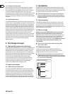
For example, when the simplest of all oscillations, a sine wave with a xed
frequency f, is overdriven, new oscillations with frequencies of 2*f, 3*f,
etc. (integral multiples of the original frequency) are produced. Thesenew
frequencies are referred to as upper harmonics grouped as odd and
evenharmonics.
Unlike the transistor, saturated tubes mostly produce even harmonics which
are perceived by the human ear as more pleasant in sound than odd harmonics.
Another important aspect lies in the fact that tubes produce distortion more
gradually than transistors, which is why we speak of the “saturation” of a tube
stage. When you overdrive a transistor you get a sudden square deformation
of the sine signal applied at the input, which produces an extreme harmonic
spectrum at the output.
Non-linear distortions are measured with a distortion factor that consists of the
total harmonic distortion [k] and partial harmonic distortions [kn]. The latter are
dened as the ratio between the voltage of a single harmonic and the voltage of
the distorted overall signal. Thus, the content of even harmonics is expressed as
k2, k4, ... and that of odd harmonics as k1, k3, ... .
U
U
n
k
n
=
Formula for calculating partial harmonic distortion
The total harmonic distortion is the root of all squared distortion factors of the
second and third degrees. Since the higher harmonics have only little impact on
the measured results, they can be neglected.
k = k
2
2
k
2
3
+
Formula for calculating total harmonic distortion
In tube circuits the distortion factor k2 is used to describe an eect which the
human ear classies as “pleasant”. Also the frequency bands in which distortion
occurs play an important role because the human ear dierentiates very clearly,
in particular, in the frequency range of human speech.