


9 ULTRAGAIN PRO MIC2200 User Manual
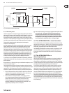
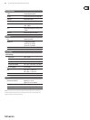
output
For unbalanced use, pin 1 and pin 3
have to be bridged
1 = ground/shield
2 = hot (+ve)
3 = cold (-ve)
input
12
3
1
2
3
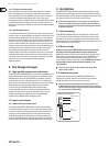
Balanced use with XLR connectors
Fig. 3.1: Dierent plug types
◊ Never use unbalanced XLR connections with microphone cables, as this
would short-circuit any phantom power transmitted over these cables!
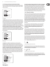
4. Control Elements
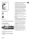
4.1 Front panel control elements
(1) (4)
(2) (5) (7)(3) (6) (8) (11) (12) (14)(9) (13)
(10) (15)
Fig. 4.1: Control elements on the front panel
(1) This +48 V switch activates the +48 V phantom power circuit that uses
the signal leads to supply condenser microphones with the required
operatingvoltage.
◊ Please check the connected signal source for matching specifications
before you switch phantom power on, so as to avoid damage to the
microphone, etc.
(2) Use the MIC/LINE switch to toggle between MIC and LINE modes. When the
switch is pressed, the unit works in MIC mode (now you can press the +48 V
switch if required; in LINE mode this function is disabled).
◊ Please note that the input phone jack is disabled in MIC mode,
i.e. you must use the XLR connector to access the microphone amp.
(3) The MIC GAIN control is enabled in MIC mode only and allows for applying
gain from 10 to 60 dB to the input signal. In view of the extremely high gain
levels that can be applied, you should verify that the gain control is properly
set before you power up the unit. In case of doubt, set the control fully
counter-clockwise, and start from there slowly raising the gain. High gain
settings and the resulting levels can damage subsequent devices.
(4) The CLIP LED signals that a level of at least +18 dBu is present after the
microphone amp stage. With too high a level the CLIP LED warns you to
reduce the gain with the MIC GAIN control, so as to avoid distortion caused
by overloading. During normal operation, the LED should not light up at all.
(5) With the PHASE REV. switch the input signal is reversed in phase by 180°.
This function is available both in MIC and LINE modes.
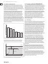
(6) When the high-pass lter is switched on (LO CUT switch pressed),
theFREQUENCY control denes the lter’s cut-o frequency. With a setting
range from 12 to 320 Hz the lter’s main task is to eliminate bottom-end
rumble noise, etc.
(7) The LO CUT switch activates/deactivates the high-pass lter.
The following 6 control elements refer to the parametric
equalizer only.
(8) The FREQUENCY control is used to select the frequency to be modied.
Please note that the frequency range can be lowered/raised with the
switches x0.1 and x10. In this way, you can process the entire audio range
between 10 Hz and 20 kHz. With both switches out, the FREQUENCY control
can be swept over a range from 100 Hz to 2 kHz.
(9) The x 0.1 switch lowers the working range of the FREQUENCY control to
10 - 200 Hz, so that you can process the bass end of the audio spectrum.
(10) The x 10 switch raises the working range of the FREQUENCY control to
1 - 20 kHz, so that you can process the treble end of the audio spectrum.
(11) The BANDWIDTH control determines the slope or quality of the lter.
Bandwidth ranges from 0.03 (Q = 43) to 2 octaves (Q = 0,67).
(12) With the LEVEL control you can set the amount of level reduction/gain
applied to the lter. The setting range is from -15 to +15 dB.
(13) The EQ IN/OUT switch activates/deactivates the parametric EQ. Please
switch the EQ o unless you need it for your specic audio application.
(14) The OUTPUT control raises/lowers the output level of the device by a
maximum of 20 dB (+/- 20 dB). With the control in mid-travel position,
nolevel change is applied. Available both in MIC and LINE modes.
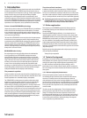
(15) The OUTPUT LEVEL LED chain displays the output level within a range from
-30 to +18 dB. The display is referenced to a level of +4 dBu.
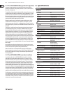
strain relief clamp
sleeve
ring
tip
sleeve
ground/shield
For connection of balanced and unbalanced plugs,
ring and sleeve have to be bridged at the stereo plug.
Balanced ¼" TRS connector
ring
cold (-ve)
tip
hot (+ve)