


7 EUROPOWER PMP2000 User Manual
behringer.com
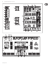
The [12] CD/TAPE/LINE IN RCA input of channel 13/14 allows you to feed in
external stereo signals from your CD player or tape deck, for example.
The [13] CD/TAPE/LINE OUT RCA output provides the stereo main mix signal of
your PMP2000 and can be routed to, say, a recording machine.
When the CD/TAPE OUT signal is connected to a tape deck whose output ◊
signal is routed back to the CD/TAPE IN on the PMP2000, feedback can
be produced as soon as you start recording. Be sure to interrupt the
connection to the CD/TAPE IN before recording!
The phantom power supply provides the voltage necessary for the operation [14]
of condenser microphones. Use the PHANTOM POWER switch to activate
the supply together for channels 1 - 12 (XLR connector). The LED above the
switch is lit when phantom power is on.
This is the PMP2000’s graphic stereo equalizer, which comprises two units [15]
and can be used to adapt the sound to the room acoustics.
The stereo equalizer is effective on the main mix when both units have been •
activated with the EQ IN buttons (16) and the MODE switch (21) is set to its
upper position (“LEFT/RIGHT”).
The stereo equalizer uses one unit each to process the main and monitor •
mix signals, if both units are on and the MODE switch (21) is set to its lower
position (“MON/MAIN”).
Use the [16] EQ IN buttons to switch the two equalizer units on or off.
Press the [17] RUMBLE FILTER button to activate the low-cut filter of
channels 1 - 6. This filter eliminates unpleasant bass frequencies
(e.g. microphone pop noise).
The [18] FX TO MON control determines the effects intensity of the multi-effects
processor as part of the monitor mix. Turn the control fully counter-clockwise
to add no effect to the monitor mix.
The [19] MONITOR LEVEL control adjusts the volume of the monitor mix.
Use the [20] MONITOR LEVEL display to control the monitor signal level.
The upper LED (LIM) lights up when the built-in limiter is activated, thus
protecting against overload.
With this [21] MODE switch you can determine whether the PMP2000 works as a
stereo amplifier (“LEFT/RIGHT”) or as a dual mono amplifier (“MON/MAIN”).
Please note that the equalizer function also depends on this switch setting
(see (15)).
The [22] FX TO MAIN control functions as FX return for the built-in effects
processor. Use this control to add the desired effect signal to the main mix.
No effect signal is added when the FX TO MAIN is set fully counter-clockwise.
The [23] MAIN LEVEL control governs the overall volume of the PMP2000.
The [24] MAIN LEVEL display reads the output level of the PMP2000. The upper
LED (LIM) lights up when the built-in limiter is activated, thus protecting
against signal peaks.
Use the [25] FX FOOTSW(itch) jack to connect any commercially available foot
controller. It allows you to bypass the effects unit.
This is the balanced [26] MONITOR output of your PMP2000. Use it to feed an
external monitor amp or active wedge.
These two [27] ¼" TS jacks allow you to route the output signal to an external
amplifier. This allows you to, say, use only the mixing and effect section of
the PMP2000. The signal is taken pre-power amp. Of course, you can also use
only the left jack as a mono output.
These two [28] ¼" TS jacks can be used to connect external signals, such as the
main mix signal from an additional mixing console (pre-power amp).
Here, you will find a list of all multi-effect presets available.[29]
This is the [30] LED level meter of the effects processor. Please make sure
that the clip LED lights up with signal peaks only. If it is lit constantly,
this indicates that the effects processor is overdriven, which can lead to
unpleasant distortion.
The Effect display reads the currently selected preset. [31]
Turn the [32] PROGRAM control to select the effect presets. Press the control
briefly to confirm your selection.
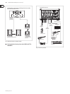
Rear panel 2.2
The mains connection is on a standard IEC receptacle. An appropriate power [33]
cord is supplied with the unit.
FUSE HOLDER[34] . Before connecting the unit to the mains, ensure that the
voltage setting matches your local voltage. Blown fuses should only be
replaced by fuses of the same type and rating.
Use the [35] POWER switch to put your PMP2000 into operation. The POWER
switch should always be in the “Off” position when you are about to connect
your unit to the mains.
Attention: The POWER switch does not fully disconnect the unit from ◊
the mains. Unplug the power cord completely when the unit is not used
for prolonged periods of time.
This is the [36] RIGHT/MONO MAIN loudspeaker output of your PMP2000,
where you can connect the right loudspeaker of a stereo system. For this
purpose, switch (21) must be set to its upper position. If, however, you run a
mono main mix (switch (21) set to its lower position), this loudspeaker output
provides the main mix signal in mono.
The impedance of the loudspeaker connected here must not fall ◊
below 4 Ω.
The [37] BRIDGE loudspeaker output allows you to combine the left and
right stereo channel in one mono output, which is useful for applications
that require the use of one loudspeaker only. To use the BRIDGE output,
switch (21) must be set to “LEFT/RIGHT”.
Always connect the BRIDGE jack to a loudspeaker with a minimum ◊
impedance of 8 Ω!
Please note that the power delivered to the speaker connected to ◊
the BRIDGE output is considerably higher than the power provided to
the speakers wired to the parallel speaker outputs. Please read the
information given on the rear panel of your PMP2000.
When using the BRIDGE loudspeaker output, NEVER use any of the ◊
other two connectors (RIGHT/MONO MAIN and LEFT/MONITOR) at the
same time!
This is the [38] LEFT/MONITOR loudspeaker output of your PMP2000, to which
you can connect the left loudspeaker of a stereo system (switch (21) set to
its upper position). If you do a main mix in mono (switch (21) set to its lower
position), this loudspeaker output provides the monitor signal in mono.
The impedance of the loudspeaker connected here must not fall ◊
below 4 Ω.
Information on how to properly connect your speaker with regard to ◊
polarity can be found on the rear of the unit (PIN assignment).
SERIAL NUMBER[39] .