


9 EUROPOWER PMP2000 User Manual
behringer.com
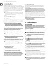
strain relief clamp
sleeve
tip
sleeve
pole 1/ground
tip
pole 2
The footswitch connects both poles momentarily
¼" TS footswitch connector
Fig. 4.4: ¼" TS connector for footswitch
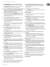
Loudspeaker connections4.4
Your EUROPOWER is equipped with high-quality Neutrik Speakon-compatible
loudspeaker connectors, which ensure safe and trouble-free operation.
The Speakon connector was especially developed for high-power loudspeakers.
Once it is plugged in, it safely locks into position and cannot be accidentally
disengaged. It prevents the occurrence of electrical shock and ensures the
correct polarity. Each of the connectors carries only the assigned single signal
(see tab. 4.1/fig. 4.6 and the information on the rear panel of the power mixer).
1-
2-
2+
1+
1-
2-
2+
1+
front view rear view
Professional speaker connector
(compatible with Neutrik Speakon connectors)
Fig. 4.5: Loudspeaker connector
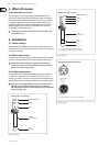
Please be sure to only use commercial Speakon cables (type NL4FC)
for connecting your loudspeakers to the PMP2000. Please check the pin
assignment of your loudspeakers and cables dependent on the PMP2000 speaker
output you choose.
1+ 1- 2+ 2-
RIGHT/MONO MAIN POS NEG — —
LEFT/MONITOR POS NEG — —
BRIDGE POS NEG — —
Tab. 4.1: Polarity configuration of speaker connectors
BRIDGE
+1
+2
16 Ω
8 Ω
LEFT/MONITOR
+1
-1
16 Ω
8 Ω
4 Ω
+1
-1
16 Ω
8 Ω
4 Ω
RIGHT MONO MAIN
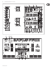
Fig. 4.6: PMP2000 loudspeaker connector assignment
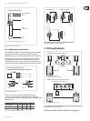
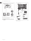
Wiring Examples5.
Loudspeaker connection (FOH mix)
PMP2000
rear panel
(part view)
2 x BEHRINGER EUROLIVE
Stack (B1500 & B1020, both passive)
Loudspeaker connection (monitor mix)
PMP2000 front panel (part view)
2 x BEHRINGER B300 (active)
Footswitch
Fig. 5.1: PMP2000 as stereo amplifier (example)
Please set the MODE switch ◊ (21) to “LEFT/RIGHT” for this application