


behringer.com
22 EURODESK SX4882 User Manual
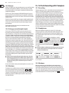
Returns14.3
Channels 1 to 8: When you’ve only got eight tape returns, you can aord to bring
them back on main channels to enable e.g. chorus vocal comps. or recorded
real-time mixing eects such as frequency sweeping to be quickly bounced or
sampled o via subgroups.
Channels 9 to 23: The most important SYNTH/SAMPLER outputs. Those most
likely to need full EQ or to be recorded to tape. You might have one Minimoog,
but half-a-dozen uses for it. Put it on an A-channel. You’ll want to record and/or
sample it in action.
Channel 24 is of course the MIC input. A compressor might be patched into the
channel 24 insert. Keep this channel free until the mix absolutely demands its
services, just in case you want to add in any last minute singing, or any last
minute anything!
The B-channel line inputs (tape returns) can accomodate even more
MIDI expanders and synths, etc.
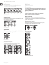
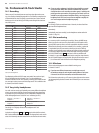
Lining up record/sample inputs14.4
Set the relevant TAPE OUTPUT and INPUT switches (located at the rear of
the console) to match the operating level of your 8-track (consult manual,
“phone manufacturer”, or simply “suck & see” to nd which setting works best).
The sampler’s variable input gain range should be more than wide enough to
accept either -10 dBV or +4 dBu. There is no oscillator in the EURODESK SX4882,
but you can use a simple unmodulated sustained tone from a keyboard.
Choose one around 1 kHz (B above middle C is 997 or 1002 Hz depending on
whether you are using the tempered scale or “just” tuning: either way it’s close
enough for jazz). Set the channel EQ to OFF, and line up the channel according
to the “Setting up procedure” (section 13.1). Route this signal to all subgroups
and adjust the SUBGROUP OUTPUT FADERS until the bargraph meters read 0 dB.
Now put the recorder into INPUT mode on all channels, and the sampler into
SAMPLE mode. If the tape operating level switches are correctly set, then 0 dB on
the subgroup output meters should also show 0 dB on the tape recorder’s input
meters. A discrepancy of +/-14 dB indicates a wrong operating level selection.
Small discrepancies may be taken up by the SUBGROUP FADERs, though a better
solution would be to get the multitrack, properly aligned. (Refer to multitrack
manual and/or qualied personnel.) Adjust the sampler’s input level until it
also reads 0 dB.
Beware of inaccurate/uncalibrated sampler input meters. Work out ◊
how hard you can safely drive the sampler’s input, reference this to
0 dB on a EURODESK subgroup meter, then take note of the sampler’s
input gain pot setting. (Or use soft adhesive tape etc. to hold it in
one position.)
(For more info on digital metering and associated problems see section 13.2.3.)
Mixdown14.5
The situation here is no dierent from record, really, save that the subgroups
may now be routed directly to the main mix (L/R) bus (
S 35
to
S 38
) for
easier mixing. Remember, you started o with the tape returns coming up on
A-channels 1 to 8, therefore there is no need to “ip” them. You will probably
(denitely) be running lots of MIDI sequencer tracks live. Take care not to
encourage MIDI delays.
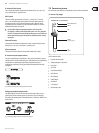
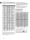
16-Track Recording with 2 Samplers15.
Recording15.1
Subgroup outputs/tape sends 1 to 16 should be wired to the multitrack record
inputs 1 to 16. Sampler inputs should be connected to subgroup outs 5, 6,
7 and 8 via custom-made Y-adaptors. Lining up is as per the previous example
(see section 14.3). When choosing which outputs where to assign, you have
to consider that you have got maybe 16 tape and 16 or 20 sampler outputs to
accommodate onto 24 A-channels (and 24 B-channels)! We’d suggest all audio
tape tracks be returned on A-Channels, while at least one stereo output from a
sampler is also brought back on a pair of A-channels for “ying in” (a sampler can
pick up e.g. chorus vocal and drop it into all choruses, or sample a particularly
nifty bit of anging on a drum loop etc.; then lay the eected loop back to tape,
without re-patching). Most other sampler outputs and MIDI keyboards which
need to be heard but not recorded can be assigned to B-channels. The remaining
six or so A-channels may then be used for overdubs.
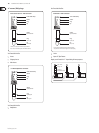
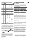
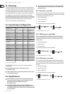
Headphones15.2
While auxless headphone monitoring (see section 14.2) is still an option
(and a pretty good one), a small general purpose studio might require a more
straightforward way of working using one or two discrete headphone mixes.
Here, it would be best to keep aux sends 1 and 2 free for monitoring purposes
until mixdown time.
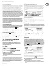
Aux returns 3/4/5//6 can be routed directly to headphones 1 and/or 2.
A good idea would be to drive
HP 2
from a combination of aux return 3 (
S 55
)
and MIX-B (
S 76
), while
HP 2
picked up its signal from aux return 4 (
S 69
)
and MIX-B (
S 88
). Channel auxes 3 and 4 would be routed to A-channels.
In this conguration a reasonable degree of balancing between the MIX-B and
aux 3/4 level into the cans is possible by adjusting
P 55
/
P 68
(minus innity
to +15 dB).
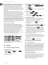
With the headphone configuration shown below, there is no easy way ◊
to get FX returns into the cans. Bring these back on A or B channels
instead, until mixdown time.
Fig. 15.1: Headphones
Mixdown15.3
With 24 A-channels and up to 36 signicant tape and sampler tracks to
accommodate, some thought will need to be given to mixdown assignments.
Tracks which need little EQ and no access to the main track reverbs/echoes on
auxes 1 and 2 may be parked on B-channels. Lead tracks and prominent rhythm/
melodic voices should be placed onto A-channels. Remember that auxes 3/4/5/6
can be dedicated either to A or B-channels by SOURCE switch
S17
.