


25 EURODESK SX4882 User Manual
behringer.com
Using this setup, you can even change the P.A. to a quadrophonic system.
Positioning takes place by balancing the main mix (channel fader, PANpot
P 24
)
against MIX-B (
P 20
,
P 21
).
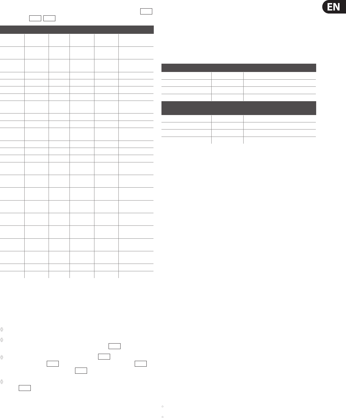
Channels Source F.O. H. FX Wedges Inlls
1 Kick MIX-B - -
Subgroups 1/2, 3/4
and 7/8
2 Snare MIX-B Aux send 4
Aux send 1
and 2
Subgroups 1/2
and 3/4
3 Hi Hat MIX-B - -
Subgroups 1/2
and 3/4
4 Tom 1 MIX-B Aux send 4 - -
5 Tom 2 MIX-B Aux send 4 - -
6 Tom 3 MIX-B Aux send 4 - -
7 Tom 4 MIX-B Aux send 4 - -
8
Cymbals
(overheads)
MIX-B - - -
9 Keyboards L MIX-B - - Subgroup 12
10 Keyboards R MIX-B - - Subgroup 12
11 Bass DI MIX-B - -
Subgroups 1/2,
3/4 and 7/8
12 Trumpet MIX-B Aux send 5 - -
13 Trombone MIX-B Aux send 5 - -
14 Sax MIX-B Aux send 5 - -
15 BVs 1 MIX-B
Aux send 5
and 6
Aux send 1
and 2
-
16 BVs 2 MIX-B
Aux send 5
and 6
Aux send 1
and 2
-
17 BVs 3 MIX-B
Aux send 5
and 6
Aux send 1
and 2
-
18 Conga L MIX-B - -
Subgroups 1/2,
3/4 and 7/8
19 Conga R MIX-B - -
Subgroups 1/2,
3/4 and 7/8
20
Guitar 1
microphone
MIX-B - - Subgroups 3 and 4
21
Guitar 2
microphone
MIX-B - - Subgroups 3 and 4
22 Lead vocal MIX-B
Aux send 5
and 6
Aux send 1 -
23 FX 1 L MIX-B - Aux send 1 -
24 FX 1 R MIX-B - Aux send 1 -
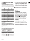
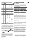
Tab. 8.2: Front/rear/stage monitors routing
For front of house route all channels to the MIX-B bus > main mix. For live P.A.
eects use auxes 3/4/5/6. For wedge monitors use aux 1 and 2 in pre mode > aux
1and 2 output. For sidells use phones 1 output. For inll for guitarist, keyboard
player and drummer use subgroups 1/2, 3/4 and 7/8.
No subgrouping is used as a mixing aid to the FOH mix.◊
Infill sends use up one group pair each as a consequence of the routing ◊
matrix being dependent on the channel PANpot (
P 24
).
All channels should be set for: aux 1/2: PRE (◊
S 13
DOWN) > WEDGES;
aux 3/4/5/6: POST (
S 16
UP) > FX; MIX-B SOURCE = CHANNEL (
S 23
DOWN); FLIP = Mic/Line SIGNAL (
S 3
UP)
In a quadrophonic setup MIX-B should be kept separate from the main ◊
mix (
S 48
UP).
OK: This example has been extreme. Chances are if you were touring with the
sort of PA / multitrack described above you’d also have a massive FOH console,
separate foldback mixer, and a rider that would make Bill Graham blanche.
None of the applications examples are designed to be used as a BLUEPRINT.
Rather, they should give you some idea of the scope and exibility of your
EURODESK SX4882. Use your imagination to nd novel ways of solving problems
and creating extra facilities.
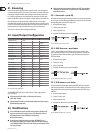
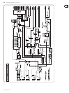
Expanding the EURODESK19.
Connections19.1
The EXPANDER PORT is input only, and provides access to all but the PFL/SOLO
buses. Since the nominal internal operating level of your EURODESK SX4882 is
0 dB, and that at the jack outputs +4 dB, the sends from the outputs of console
2 must be attenuated by +4 dB if unity gain between it and the primary console
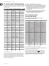
is to be maintained. Wiring is as follows:
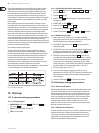
EURODESK 2 > -4 dB > EURODESK 1
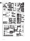
Subgroup outputs 1 to 8 EXPANDER PORT subgroup inputs 1 to 8
Aux outputs 1 to 6 EXPANDER PORT aux inputs 1 to 6
Main mix output EXPANDER PORT main mix inputs
MIX-B output EXPANDER PORT MIX-B input
Another manufacturer’s
desk
> -X dB > EURODESK 1
Subgroup outputs 1 to 8 EXPANDER PORT subgroup inputs 1 to 8
Aux outputs 1 to 6 EXPANDER PORT aux inputs 1 to 6
Main mix output EXPANDER PORT main mix inputs
MIX-B output EXPANDER PORT MIX-B input
Alignment19.2
To nd out the value of “X” align the consoles in the following way. Patch a 1 kHz
sine tone (or play a sustained B above middle C on a keyboard) into a channel
on each console. Set up each console so that the signal produces unity gain
(0 dB) at every output (use each console’s PFL or equivalent function to do this).
Now, connect the outputs of the second console into the EURODESK EXPANDER
PORT. Mute the channel on the EURODESK carrying the signal, and look at the
EURODESK outputs. Systematically adjust the reading on each bus until they all
read 0 dB by adjusting the master send levels of console 2 (i.e.: master aux send
controls, main mix master faders, subgroup faders, etc.).
Timecode20.
In analog multitrack recording timecode usually goes down on the edge of the
tape: track 8, 16 or 24, with the adjacent track left clear (GUARD BAND) to stop
bleeding between recorded tracks and code. Digital formats do not waste any
audio tracks on timecode: a separate sync is provided.
Ideally, timecode should be patched from the multitrack out directly into the
synchronizer input. Normally, a 24 track tape is striped with timecode before a
session commences. Any sequenced music, click track, mix automation is then
referenced to it.
Always check sync before laying down any sequenced music: record a click
track, then check to see that a “live” playback doesn’t drift. Timecode comes
in various formats. The general rule is: format (and make/model) of timecode
generator must be matched to the reader. This shouldn’t be a problem if
recording and mixing take place in-house and under one roof. It’s when tapes
move around that problems arise (be sure to include every conceivable technical
detail on a tracksheet accompanying the master tape). Fortunately, there are
ways to generate fresh in-sync timecode even where none existed in the
rst place, otherwise most remixes would never happen. You would rather
not have to, though, since it takes time, eort, and an intelligent “learning”
synchronizer to do it.
If the gain from the recorder is too low to drive the sync unit,
re-stripe at a higher level or •
amplify the recorded timecode somehow, possibly via a desk channel not •
routed to any of the main buses. In this case use the channel’s direct out to
drive the synchronizer’s input, in order to keep the timecode as remote as
possible from the audio (timecode crosses over like nothing else we know).